Status Reporting 51
4
Status Reporting
Power Supply Status Structure
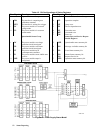
Figure 4-1 shows the status register structure of the power supply. The Standard Event, Status Byte, and Service Request
Enable registers and the Output Queue perform standard GPIB functions as defined in the IEEE 488.2 Standard Digital
Interface for Programmable Instrumentation. The Operation Status and Questionable Status registers implement status
functions specific to the power supply. Table 4-2 and Figure 4-1 show the bit configuration of each status register.
Operation Status Group
Register Functions
The Operation Status registers record signals that occur during normal operation. The group consists of the following
registers:
• A Condition register that holds real-time status of the circuits being monitored. It is a read-only register.
• A PTR/NTR (positive transition/negative transition) Filter that functions as described under
STAT:OPER:NTR|PTR COMMANDS in "Chapter 3 - Language Dictionary". This is a read/write register.
• An Event register that latches any condition that is passed through the PTR or NTR filters. Reading the Event
register clears it.
• An Enable register that functions as described under STAT:OPER:ENAB in "Chapter 3 - Language
Dictionary". This is a read/write register.
The outputs of the Operation Status group are logically-ORed into the OPER(ation) summary bit (7) of the Status Byte
register.
Register Commands
Commands that access this group are derived from the STAT:OPER commands described in "Chapter 3 - Language
Dictionary" and summarized in Table 4-1.
Table 4-1. Status Operation Commands
Register Command Query Cleared By
Condition (None)
STAT:OPER:COND?
Cannot be cleared
PTR Filter
STAT:OPER:PTR <NRf>
STAT:OPER:PTR? Programming 0
NTR Filter
STAT:OPER:NTR <NRf>
STAT:OPER:NTR?
Programming 0 or
STAT:PRES
Event (None)
STAT:OPER:EVEN? Reading or *CLS
Enable
STAT:OPER:ENAB <NRf>
STAT:OPER:ENAB?
Programming 0


