E - IEC Mode Command Summary
170
CALCulate:LIMit:UPPer
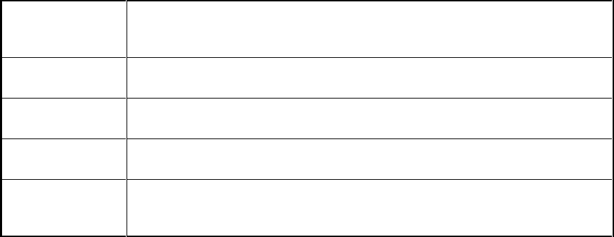
This command sets various limits associated with rms voltage fluctuations testing for IEC 1000-3-3. as
described in the following table. All five parameters are type NRf. The order in which the five parameters
are entered must correspond to the order in the table.
vss delta
Sets the maximum peak-to-peak variation of relative voltage
1
that defines
“steady-state”. At *RST this value is set to 0.003
2
. Note that this number is
not specified by IEC 1000-3-3.
dmax limit
Sets the maximum relative voltage
1
change allowed before a dmax error is
flagged. At *RST this value is set to 0.04 (see note
2
).
dc limit
Sets the maximum relative steady-state voltage change allowed before a dc
error is flagged. At *RST this value is set to 0.03 (see note
2
).
dt tlimit
Sets the maximum time in seconds that the relative voltage
1
can exceed the
dt limit before a dt error is flagged. At *RST this value is set to 0.2 seconds.
dt limit
Sets the maximum relative voltage
1
that must be exceeded for dt tlimit
seconds before a dt error is flagged. At *RST this value is set to 0.03 (see
note
2
).
1
The expression “relative voltage” as used above is the measured rms voltage divided by the programmed
voltage.
2
This value is the ratio with respect to U
n
(the European nominal line voltage). For example, a value of .03
represents 6.9 volts if U
n
= 230 volts. (Ratio * 100 = % of U
n
)
Command Syntax
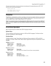
CALCulate:LIMit:UPPer[:DATA] <NRf>,<NRf>,<NRf>,<NRf>,<NRf>
Parameters
See
table
*RST Value
See
table
Examples
CALC:LIM:UPP .003, .04, .03, .2, .03
Returned Parameters
<NR3>


