


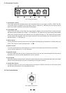
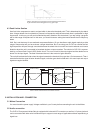

5. SC Filter switch
Engaging this switch to insert a Low-cut filter in the sidechain path and thus limits the influence of low frequencies
on the CLE 8.0's control processes.
6. Smart switch
Engaging this button to switch the "Hard Knee" characteristics to SKC (Smart Knee Control). SKC provides a
compression of the program material and should therefore be used whenever compression should be more or
less inaudible.
7
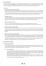
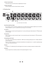
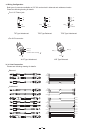
1. Gain Reduction Meter
It indicated the gain reduction. The range displayed is 1 to 30 dB.
2. Input / Output Level Meter
It will read the actual Input or Output Level. The range goes from -24dB to +18dB.
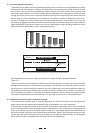
3. Bypass Switch
This switch simply turns off the correspondent channel. It can also be used to make an A/B comparison in between
processed and unprocessed signal.
4. Input / Output Meter Switch
7. Link CH 1 switch
Every channel contains the Link CH1 switch except the CH1. Activating this switch will link the corresponding
channel to CH1, and the CH1 will take control of the corresponding channel.
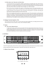
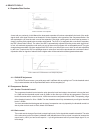
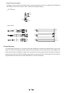
3.2 Expander / Gate Section
Pic.3: Expander/Gate Section
10
8
9
8
1.5
1.2
7
2.5
0
EXP/GATE(dB)
45
OFF +15
RATIO(1:N)
9. Ratio Control
This control determines the expansion ratio when the signal drops below the threshold level. The expansion ratio can
be set from 1:1.2 to 1:8 (Low ratio for Expander application or 1:8 for Gate application).
10. Threshold LED
The "+" Led lights up when an audio signal is below the set threshold. The "-" Led lights up in presence of an
expansion
8. EXP/GATE control
This control adjust the threshold level for the Expander / Gate Section in the range of Off to +15dBu. Signals
below this level cause expansion.
When the switch is ON the level indicator will read the input level. When it is OFF the level indicator will read
the output level.