


6
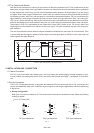
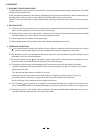
3. CONTROL ELEMENTS
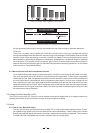
Your CLE 4.0 presents with four channels. Each channel is equipped with the same control elements: 3 push-button
switches, 4 rotary controls and 17 LEDs. You can operate in stereo mode via pressing the Couple switch. The details
please refer to following content.
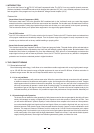
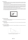
1. Threshold Control for Compressor Section
With this control you will adjust the threshold level in the Compressor. The range is varied from -40dBu to +20dBu. When
a signal exceed the set threshold by 10dB maximum the SKC will be applied, while above such level signal will be processed
with hard knee compression.
8
R
LTO
LIMITER
dBu
BYPASS
dBu
N:1
dBu
N:1
I/O METER
THRESHOLD
RATIO
COMPRESSOR
RATIO OUTPUT GAIN
dBu N:1
THRESHOLD
RATIO
COMPRESSOR
OUTPUT GAIN
COMPRESSOR
LIMITER
THRESHOLD THRESHOLD
dBu
LIMITER
SMART
I/O METER
BYPASS
SMART
COUPLE
CH1 MASTER
COUPLE
CH3 MASTER
OUTPUT GAIN
THRESHOLD
dBu
1
20
40
10
10
20
2
2.5
20
10
10
0
OFF
0
12
BYPASS
I/O METER
SMART
CH1 CH2 CH 3
THRESHOLD
dB dB
dB
30
40
10
10
20
30
1
2
2.5
20
20
10
10
0
dB
OFF
0
12
40
10
10
20
30
1
2
2.5
20
20
10
10
0
OFF
0
12
GAIN REDUCTION(dB) INPUT / OUTPUT LEVEL(dB)GAIN REDUCTION(dB) INPUT / OUTPUT LEVEL(dB)GAIN REDUCTION(dB) INPUT / OUTPUT LEVEL(dB)
30 25 20 15 10 6
3
1
12 0 LIM1261824
6
18
30 25 20 15 10 6
3
1
12 0 LIM1261824
6
18
30 25 20 15 10 6
3
1
12 0 LIM1261824
6
18
10
4
18
10
410 4
18
LIMITER
dBu
BYPASS
N:1
I/O METER
THRESHOLD
RATIO OUTPUT GAIN
CLE 4.0
Quad
Compressor/
Limiter
ON
OFF
COMPRESSOR
THRESHOLD
dBu
SMART
CH4
POWER
dB
40
10
10
20
30
1
2
2.5
20
20
10
10
0
OFF
0
12
GAIN REDUCTION(dB) INPUT / OUTPUT LEVEL(dB)
30 25 20 15 10 6
3
1
12 0 LIM1261824
6
18
18
10
4
18
7
10
1 5 2 6 3 4 9
11
13
12
14
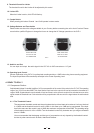
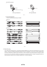
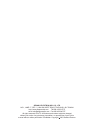
OPERATING LEVEL
RING/PIN 3
SLEEVE/PIN 1
TIP/PIN 2TIP/PIN 2
RING/PIN 3
SLEEVE/PIN 1
CHANNEL4 CHANNEL3
CHANNEL2 CHANNEL1
OUTPUT
INPUT
OUTPUT
INPUT
OUTPUT
INPUT
OUTPUT
INPUT
dBu4
10dBV
dBu4
10dBV
OPERATING LEVELOPERATING LEVEL
14W
AC INPUT
95-120V /210-240V 60-50Hz
Rated Power Consumption
FUSE:
210-240V: T315mAL 250VAC
95-120V: 630mA 250VAC
REPLACE FUSE WITH
CORRECT TYPE ONLY
2
1
3
2
1
3
2
1
3
2
1
3
TIP/PIN 2
RING/PIN 3
SLEEVE/PIN 1
dBu4
10dBV
OPERATING LEVEL
TIP/PIN 2
RING/PIN 3
SLEEVE/PIN 1
dBu4
10dBV
110-120V
220-240V
2. Ratio Control
The ratio in between input and output level signals above the set threshold is determined by this control. When the
SKC is applied such ratio is only expressed for the signals exceeding the set threshold more than 10dB. The range
of control of the ratio varies from 1:1 to :1.
3. Output Gain Control
You can increase or decrease the output signal by a maximum of 20dB. IN such a way you can recover a level lost
during the compression process.
5. Smart Switch
A hard knee compression is turned into SKC by mean of this switch. If you wish to get a compression that is quite
inaudible use the SKC mode through the Smart switch.
4. Bypass Switch
Push this switch and you will deactivate the corresponding channel. You can also use the bypass switch to make an A/B
comparison in between processed and unprocessed signal.
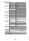
6. Meter Switch for input / output
When this switch is ON the Meter will read the output level. When the switch is OFF, the Meter will read the input
level.
7. Level Meter for Input / Output
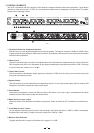
You can adjust the operating level by mean of the Operating Level Switch and choose -10dBV or +4dBu. Consequently
the Meter will be the Input or Output Level with a range from -24dB to +18dB.
8. Meter for Gain Reduction
The gain reduction will be shown by this Meter with a range of 1 to 30dB.
Pic. 1