


Evaluation Board User Guide UG-065
Rev. 0 | Page 3 of 8
OVERVIEW
The ADXL345 inertial sensor development board has the
following features:
• A 2-layer printed circuit board (PCB), 1.125-inches × 2.25-
inches form factor
• A two AAA battery power supply
• A 4-pin UART header to connect to RS232 interface cable
• Reset/download push-buttons
• Power indicator/general-purpose LEDs
• Access to all microcontroller I/Os from the external
header; all device pins are brought out to the external
header pins
• Demonstration firmware
FEATURES
Power Supply
A pair of AAA batteries powers the board, and the battery
holder is located on the back of the board. An on/off switch on
the lower left of the front of the board controls power to it. The
battery voltage is not regulated but is decoupled with a 10 µF
capacitor globally, and an additional 1 µF capacitor at the device
supply pins to ground.
RS232 Interface
The ADuC7024 (UC1) P1.1 and P1.0 lines are connected to the
RS232 interface cable via the connector (UART). The interface
cable generates the required level shifting to allow direct
connection to a PC serial port. Ensure that the supplied cable
is connected to the board correctly, that is, V
DD
is connected to
V
DD
and GND is connected to GND.
RESET/PROG Push-Buttons
A RESET push-button is provided to allow the user to manually
reset the part. When inserted, the RESET pin of the ADuC7024
is pulled to GND. Because the RESET pin on the ADuC7024 is
Schmitt-triggered internally, there is no need to use an external
Schmitt trigger on this pin.
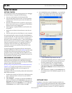
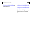
To enter serial download mode, the user must hold the P0.0/BM
pin low while reset is toggled. On the development board, serial
download mode can be easily initiated by holding down the
serial download push-button (PROG) while inserting and
releasing the reset button (RESET), as illustrated in Figure 2.
Power Indicator/General-Purpose LEDs
Two general-purpose LEDs are available on the board. A red
LED (LED1) is connected to P4.5 of the ADuC7024, and a
green LED (LED2) is connected to P4.4. Both LEDs can be
repurposed via firmware.
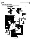
Breakout Header
All ADuC7024 pins are brought out to headers on either side of
the board. The headers come unpopulated but can be populated
using standard 0.1-inch header pins.
The thin form factor of the top of the board allows the design of
an expansion board to connect above the development board,
with the header pins providing both electrical and physical
connections.
Firmware
Sample firmware is provided on the ADXL345 product page.
08658-002
RESET PROG
(A) RESET
AND PROG RELEASED
RESET PROG
(E) RELEASE PROG
RESET PROG
(B) PUSH PROG
RESET PROG
(D) RELEASE RESET
PROG
(C) PUSH RESET
RESET
Figure 2. Entering Serial Download Mode to Reprogram the Board