


UG-065 Evaluation Board User Guide
Rev. 0 | Page 4 of 8
USING THE BOARD
GETTING STARTED
The development board comes preprogrammed as a datalogger
at a 100 Hz datarate. To log data, do the following:
1. Insert two AAA batteries into the battery holder.
2. Insert the MicroSD card into the slot. The card should be
formatted with a FAT32 file system; most microSD cards
come this way.
3. Push the on/off switch to the on position to power up the
board. The red LED turns on, and the green LED blinks to
indicate that the board is logging data.
4. When logging is completed, slide the on/off switch to the
off position.
5. Remove the card from the slot and insert it into the card
reader.
6. Insert the card reader into the USB port on your computer.
The acceleration log file is written to the path \XL345\DB0001.txt
on the microSD card. The data in the text file consists of a set of
comma-separated t, x, y, and z values, where t corresponds to
time and x, y, and z correspond to the x-, y-, and z-axis acceleration
data for each time point. Acceleration values are logged in LSB,
where the nominal scale factor is 3.9 mg/LSB. To convert an
acceleration value from LSB to mg, simply multiply by 3.9
(nominally, or measure the sensitivity of the part for a more
accurate conversion).
To plot the logged data using Microsoft Excel, download the
XL345DB_DataPlotter.xls file from the ADXL345 product page
and follow the instructions described in the file. Users are
prompted to browse to their logged data file (DBxxxx.txt), the
data is imported and plotted in a new workbook, and users are
then prompted to save that workbook.
PROGRAMMING THE BOARD
The board can be repurposed with no programming required
using the .hex files provided on the ADXL345 product page.
The .hex files are uploaded onto the board using the ARMWSD
program, which can be downloaded at
ftp://ftp.analog.com/pub/MicroConverter/ARM%20Tools/AR
MWSDv1.8.zip. Simply unzip the folder to a known location
and open the ARMWSD.exe file to use the program. No
installation is required.
To reprogram the board, use the cable provided with the board and
follow these instructions:
1. Download the desired .hex file from the ADXL345 product
page to a known location, or locate it on your machine.
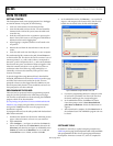
2. Open ARMWSD.
3. Click Configure… (see Figure 3) and select the Parts tab,
shown in see. Make sure the ADuC7024 is selected in the
Select Part pull-down list (see Figure 4). Additionally, in the
Comms tab, make sure the Baudrate is set to 115200, and
the Serial Port is set to COM1, and then click OK.
4. In the ARMWSD window, click Browse…, see encircled in
Figure 3, and navigate to the location of the .hex file to be
loaded onto the board. Select the file and click Open.
08658-003
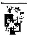
Figure 3. ARMWSD Window
08658-005
Figure 4. ARMWSD Configure Window: Parts Tab
5. Connect the programming cable to the serial port on the
PC and to the 4-pin header near the on/off switch on
the board, matching up the corresponding pins.
6. In the ARMWSD window, click Start. The Status
frame then prompts users to Press Download and
pulse Reset on Hardware. Follow the illustrations in
Figure 2.
7. When download is complete, click the Reset button on
the evaluation board. The ARMWSD program can now
be closed.
SOFTWARE TOOLS
In addition to the ready-to-upload examples provided on the
ADXL345 product page, the development board is fully modifiable
and reprogrammable to allow for easy prototyping and firmware
development. Firmware is written in C, and it is compiled for