


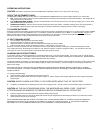
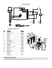
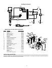
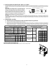

WIRING DIAGRAM
8
1
YELLOW
GRAY
BROWN
FAN
TRANSFORMER
RESISTOR
RECTIFIER
AMMETER
DC
CIRCUIT
BREAKE
R
POSITIVE
(RED)
NEGATIVE
(BLACK)
AC CIRCUIT
BREAKER
4
2
6
WHITE
GREEN
BLACK
TIMER
456
YELLOW
BLACK
WHITE
YELLOW
WHITE
BLACK
BLACK
1
2
3
VOLTS
CHARGE
SWITCH
ORANGE
VIOLET
JAW GUIDE
PROBE
"STOP/GO LIGHT"
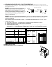
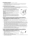
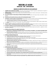
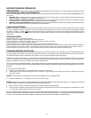
MODEL 6009 PARTS LIST
Item
Description Part No.
1 Front leg ................................................... 605671
2 Wheels w/nuts (2)..................................... 611157
8
21
9
11
24
23
7
15
14
16
22
3
18
12
17
13
10
2
19
5
6
1
20
4
3 Handle ...................................................... 605213
4 Stop/Go Lite.............................................. 604579
5 Fan Blade ................................................. 610189
6 Fan Motor ................................................. 610190
7 Rectifier .................................................... 610364
8 Timer ........................................................ 611245
9 Amps Meter .............................................. 605204
10 AC Cord.................................................... 611248
11 Switch w/knob (1)...................................... 611187
12 DC Cable Set............................................ 610855
13 DC Circuit Breaker (1) .............................. 610536
14 Axle w/nuts ............................................... 610052
15 Transformer .............................................. 610819
16 AC Breaker ............................................... 603597
17 Clamps ......................................................... 6202
18 Jaw Kit (repairs 1 clamp) .......................... 610970
19 Clamp Bar................................................. 610517
20 Base ......................................................... 610054
21 Pointer Knob ............................................. 603147
22 Back Panel ............................................... 610977
23 Right Side Panel ....................................... 611032
24 Front Panel ............................................... 611250
Not shown
Top Panel ................................................. 611011
Left Side Panel ......................................... 611031
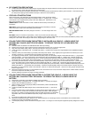
MAINTENANCE INSTRUCTIONS
Worn clamps and jaws should be replaced. Worn parts can lead to poor connections and present a safety hazard. See parts list for part number of
jaw and clamp kits. Any Maintenance or repair of this unit that involves disassembly of the cabinet should be done only by a qualified serviceman.
Incorrect reassembly may result in a risk of electric shock when the unit is subsequently used.
5