


Atlas #544099 and #447399 DCC Decoders
3
Atlas Model Railroad Co., Inc.
internal safeguards to prevent damage, you must not allow any metal
part of the locomotive to touch surface components of the decoder other
than the pickup pads on the decoder that connect to the wheel-sets, the
headlights, and the motor brushes. Any contact to other parts of the
decoder can cause a direct internal short circuit and destroy the
DCC decoder.
The Atlas #544099 and #447299 DCC decoders are not completely
protected against static electricity and have sensitive electronic parts.
When installing one of these decoders in your N scale locomotive, it is
recommended that you wear a grounded anti-static wrist strap. Also be
careful in handling the decoder, especially in the area around the top
rear part of the decoder (the area where the microprocessor is located).
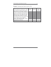
All Atlas #544099 and #447299 DCC decoders come with
two LED headlights already installed. The light outputs of
these decoders are designed only to drive these LED
headlights. The Atlas warranty is void if the LEDs are
removed from the decoder PC board.
Step by Step Installation
In the following steps, please refer to the instructions provided with your
Atlas locomotive.
1) Remove the locomotive's body shell. Use care so as not to
damage any of the fragile parts.
2) Loosen the two screws that hold the frame together; these screws
are located at the front and rear of the frame.
3) Carefully remove the lighting control circuit board, which is located
at the top of the frame.
4) Place the decoder between the two halves of the frame so that the
decoder label is at the top of the board and the two motor pads are
at the bottom of the decoder. These motor pads will connect with
the two copper motor contacts when the decoder installation has
been completed.
5) Carefully press the two frame halves together, with the sides of the
decoder inserted into the notches in the two halves of the frame.
Some pressure is needed to press the two frame halves together.
This pressure fit insures good electrical contact between the frame
and the decoder.
6) Tighten the two screws that hold the locomotive frame together.
7) Carefully check to make sure that the motor contacts are not
touching either half of the frame. It is necessary to look down from
the top through the frame cutouts in order to check for such