


Atlas #544099 and #447399 DCC Decoders
7
Atlas Model Railroad Co., Inc.
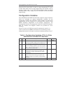
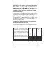
CV Description Range Default
Value
**
29
Bit 1
Headlight mode:
0 = Operation with 14 or 27 speed-step
systems. This setting is selected when the
locomotive decoder is used with any DCC
system that does not support the 28 speed-
step mode. If the headlights turn on and off
as the speed is increased, the command
station is configured for 28 speed-steps, and
the decoder is set for 14 speed-steps.
1 = Operation with 28, 55 or 128 speed
steps. If you use this setting, the Command
Station must also be configured to use either
the 28 speed-step mode or the 128 speed-
step mode; otherwise, the headlights cannot
be controlled.
0,1 1
(2)
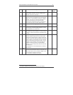
Bit 2
Usage on conventional DC layouts:
0 = locomotive operates in digital (DCC)
mode only
1 = locomotive can operate on either
conventional DC or on DCC
0,1 1
(4)
Bit 3
Bit 4
Both bitts always 0 0 0
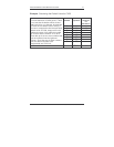
Bit 5
Extended Addressing:
0= Normal (single byte) addressing
1=Two byte extended addressing
0-1 0
(32)
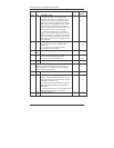
Bit 6
Bit 7
Both bits always 0 0 0
50 Decoder Configuration, Byte 2:
CV50 is similar to CV29, but CV50 is used to set
other properties. The definitions for the individual
bits of CV50 are given below.
0 or 4 0
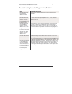
Bit 0
Bit 1
Both bits always 0 0 0
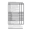
Bit 2
Brake momentum on DC operation.
Used to achieve prototypical braking at red
signal indications if conventional DC control
is disabled. (CV29.2 = 0*)
0 = locomotive proceeds with track-voltage-
dependent speed inside the conventional.
DC section.
1 = locomotive brakes in the conventional DC
section with pre set brake momentum.
0,1 0
(4)
Bits
3-7
Not used, always 0 0 0