


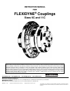


DESCRIPTION
FLEXIDYNE dry fluid couplings are a unique concept
to provide soft start and momentary overload protection for
all types of driven equipment. Standard NEMA-B motors
with RPM base speeds of 1750, 1160 or 860 are
commonly used with a FLEXIDYNE, yet other available
power sources may be used with the FLEXIDYNE.
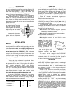
The dry "fluid" in the FLEXIDYNE is heat treated steel
shot. A measured amount, referred to as flow charge, is
added into a housing which has been keyed to the motor
shaft. When the motor is started, centrifugal force throws
the flow charge to the perimeter of the housing, packs it
between the housing and the rotor which in turn transmits
power to the load.
After the starting period
of slippage between housing
and rotor the two become
locked together and achieve
full load speed, operating
without slip and with 100%
efficiency.
Consequently, the motor
accelerates instantly to base
speed, while the load starts
gradually and smoothly.
INSTALLATION
Method 1:
Install coupling flange on motor shaft and drive
housing mechanism on driven shaft in accordance with the
instructions packaged with the TAPER-LOCK
®
bushings
(Manual #499645). Note: The coupling flange must be
mounted on motor shaft (not driven shaft) to allow
proper operation of the FLEXIDYNE. Shaft ends must
not protrude beyond bushing ends. Install coupling disc
over pins on drive housing mechanism. Position motor and
driven unit so that spacer buttons on coupling flange just
contact the drive housing and coupling flange (Reference
dimension "A" on page 5).
Method 2:
If motor and driven unit are to be positioned before
mounting FLEXIDYNE, shaft ends should be spaced apart
by dimension "B" on page 5. Slide bushing and coupling
flange onto motor shaft. Install coupling disc over pins on
drive housing mechanism. Install drive housing
mechanism on driven shaft and coupling flange on motor
shaft per instructions packed with the TAPER-LOCK
bushings, so that the spacer buttons on the coupling disc
just contact the drive housing and coupling flange
(Reference dimension "A" on page 5). Make certain that
shaft ends do not protrude beyond bushing ends.
For longest FLEXIDYNE coupling life, it is always
desirable to align coupling as accurately as possible at
initial installation. Check alignment by laying a straight
edge across the coupling flange and drive housing at
several points around the circumference.
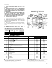
FLEXIDYNE Size 9C 11C
Dimension “A”
7
/
8
1
1
/
8
Dimension “B” 5
1
/
8
6
1
/
8
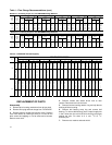
START-UP
1. Remove one of the filler plugs and install ½ the proper
amount of flow charge specified in Table 1. Replace and
tighten filler plug, making sure that no flow charge is
trapped in the threads. Remove other filler plug and install
the remaining ½ of specified amount of flow charge
repeating the same procedure. Tighten filler plug to 200
inch-pounds torque.
2. Attach AC ammeter (conventional clamp-on or
equivalent) to one line of the AC motor. Set range to cover
200% of motor nameplate current.
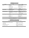
3. Note maximum allowable acceleration time for
FLEXIDYNE as stated in Tables 1 and 2. Note: Table 2
lists starting time capacity for starting cycles occurring
more than once every 2 hours.
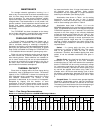
4. Push start button. Observe motor current during load
acceleration and number of seconds required to reach full
speed (Fig. 2).
Increase amount of flow charge if:
A. Acceleration time reaches maximum allowable
before load is up to speed. Turn off power
immediately if this time is reached.
B. Acceleration amperage is below motor nameplate.
Decrease amount of flow charge if:
A. Acceleration time is less than 1½ seconds.
B. Acceleration amperage is above 200% of motor
nameplate.
Caution: The rotor of the
FLEXIDYNE must slip during
acceleration to allow flow
charge to become evenly
distributed in the FLEXIDYNE
housing. Therefore, DO NOT
ALLOW FLEXIDYNE TO
RUN "FREE" (that is, without
a load on the driven end),
otherwise a dangerous out-
of-balance condition may
result.
The amount of flow charge in the FLEXIDYNE
determines the acceleration time for a given load. Longer
acceleration times will occur when less flow charge is
used and faster acceleration, from stop to full speed, will
be observed with greater amounts of flow charge.
OPERATION
The FLEXIDYNE should start the load smoothly and
without delay provided the proper amount of flow charge
has been used. Should the acceleration time exceed the
maximum allowable in Table 1, shut off power to the
FLEXIDYNE immediately. Allow the FLEXIDYNE to cool,
then add small amounts of flow charge until proper
acceleration is observed.
Vibration is an indication of accelerating too rapidly
and not allowing flow charge to become evenly distributed
in the FLEXIDYNE housing. This can be corrected by
removing small amounts of flow charge until vibration
subsides. Other causes of vibration are, undersize
shafting, unit not installed far enough on shaft, worn bore
in the unit, or mis-alignment.
Slippage – The FLEXIDYNE can, without slipping,
transmit overloads up to 130% of its present starting
torque. Should this breakaway torque be exceeded the
FLEXIDYNE will slip and generate heat (see Overload
Protection). Although slippage usually indicates increased
loads, it can also be caused by worn flow charge or a worn
rotor especially if the FLEXIDYNE has been in operation
for some time. The necessity to replace either a rotor or
flow charge will be made evident by a loss in power
transmitting capacity of the FLEXIDYNE.