


4
MAINTENANCE
For average industrial applications involving 3 or 4
starts a day of not more than 6 seconds acceleration time
each, the flow charge should be changed every 10,000
hours of operation. For more severe conditions, visually
inspect flow charge at more frequent intervals; it should be
changed when it has deteriorated to a half powder, half
granular condition. Visual inspections should continue until
enough flow charge changes have been made to
adequately establish a schedule for renewing FLEXIDYNE
flow charge.
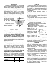
The FLEXIDYNE has been lubricated at the factory
and no further lubrication is required. Never apply grease,
oil or any other foreign material to the flow charge.
OVERLOAD PROTECTION
A Thermal Cutout is available from Dodge and is
recommended for FLEXIDYNE Size 9 where slippage
(due to overloads, starting or reversing) is frequent or
prolonged. Its function is to protect against excessive heat
which may be generated by the FLEXIDYNE, A Speed
Drop Cutout is available from Dodge for FLEXIDYNE Size
11 for installation where overloads or jamming may occur.
Either unit can be installed to send a signal to interrupt
the motor current and, if desired, activate a bell, light or
other warning device. Cutout switches are intended for
use in control circuits only and are not recommended for
dc current nor should they be used directly in the line to
the motor. Both units are available in special explosion-
proof models for hazardous atmospheres.
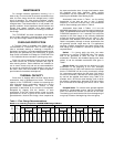
THERMAL CAPACITY
Since there is slippage within the flow charge during
acceleration, heat is generated from friction. The thermal
capacity of the FLEXIDYNE is based on balancing this
heat generated during acceleration against the cooling
time between accelerations. The amount of heat
generated is determined by the amount of horsepower
dissipated by slipping and the duration of each
acceleration. If the flow charge weight is light, the heat
generated will not be as great as that which would be
generated with a heavier flow charge, when compared at
the same acceleration time. A longer time between starts
will dissipate more heat; therefore, higher starting
horsepowers may be transmitted, or longer acceleration
times may be allowable. (See Starting Cycle)
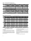
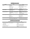
Acceleration times shown in Table 1 are for starting
frequencies of one start per hour or less. If starting
frequency is more than once per hour, use acceleration
time for actual starting cycle shown in Table 2.
Acceleration times listed in Tables 1 & 2 are the
MAXIMUM permissible for the various starting frequencies
listed. The MINIMUM acceleration time required for proper
FLEXIDYNE operation is 1 to 1½ seconds. This is the time
required for the flow charge to be uniformly distributed
around the housing cavity before the unit "locks in". Any
acceleration time between the minimum and maximum
listed is acceptable, although a shorter acceleration time
will generally provide longer wear life. For applications
requiring a specific acceleration time (within these limits)
flow charge may be added or removed to produce the
required results.
Stalled – If a jam-up stalls the drive, the motor
continues to run and the FLEXIDYNE slips. This causes
heat to be generated at twice the rate of normal
acceleration. Therefore, the allowable slipping time, when
stalled, is half the allowable acceleration time given in
Table 1.
Starting Cycle is the time from the beginning of one
acceleration to the beginning of the next. Allowable
acceleration times in Table 2 are based on the assumption
that the FLEXIDYNE will be running continuously except
for a momentary stop before the next start. If the stop is
more than momentary, decrease the actual starting cycle
by one-half the stopped time before using Table 2; far
example, with a 50 minute actual starting cycle of which
20 minutes is stopped time, decrease 50 by half of 20 to
give 40 minutes as the starting cycle time to use for Table
2.
Grouped Starts –For several starts grouped together
followed by uninterrupted running, add the acceleration
times of all starts and consider it as the time for one start.
The starting cycle would be the time from the beginning of
one group of starts to the beginning of the next group.
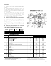
Table 1 – Flow Charge Recommendations
Based on % of Starting Torque for 1760 RPM NEMA Design B Motors
100% @ 1760 RPM 125% @ 1750 RPM 150% @ 1740 RPM 175% @ 1700 RPM 200% @ 1650 RPM
Flow
Charge
Flow
Charge
Flow
Charge
Flow
Charge
Flow
Charge
Rated
Motor
HP
FLEXI-
DYNE
Size
Start-
ing
HP
Lbs. Oz.
Max.
Time
In
Sec.
Start-
ing
HP
Lbs. Oz.
Max.
Time
In
Sec.
Start-
ing
HP
Lbs. Oz.
Max.
Time
In
Sec.
Start-
ing
HP
Lbs. Oz.
Max.
Time
In
Sec.
Start-
ing
HP
Lbs. Oz.
Max.
Time
In
Sec.
15 9C 15.0 2 9 76 18.8 3 0 58 22.3 3 7 58 25.5 3 13 39 28.3 4 2 28
20 9C 20 3 2 52 25 3 10 40 30 4 0 26 34 4 8 22 38 5 3 16
25 11C 25 4 3 98 31 4 12 76 37 5 0 55 42 5 8 42 47 6 2 37
30 11C 30 4 10 80 37 5 0 55 45 5 12 39 51 6 3 33 57 6 12 27
40 11C 40 5 5 44 50 6 0 34 60 6 8 24 68 7 3 22 75 8 0 19
50 11C 50 5 13 34 62 6 10 24 74 7 6 20 85 8 2 17 94 8 11 15
872-3