


724-746-5500 | blackbox.com
Page 7
IC408A
Chapter 2: Overview
2.4 Hardware Description
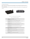
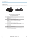
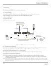
Figure 2-1 shows the front and back panels of the Local Extender Unit. Table 2-1 describes the Local Extender components.
Figure 2-2 shows the front and back panels of the Remote Extender Unit. Table 2-2 describes the Remote Extender components.
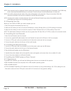
2.4.1 Local Extender
The Local Extender connects to the host computer using a standard USB 2.0 cable. Power for this unit is provided by the host
computer.
1234
5 6 7 8 9
Figure 2-1. Front and back panels of the Local Extender.
Table 2-1. Local Extender components.
Item Component Description
1 Power LED (Blue)
ON when power is supplied.
OFF when no power is supplied by the host computer.
2 Link LED (Green)
ON when valid link is established between the local and remote extenders.
Blinking when the IC408A is in a suspended state.
OFF when there is no link between local and remote extenders.
3 Host LED (Green)
ON when the IC408A system is properly enumerated on the host computer.
Blinking when IC408A LAN is in a suspended state.
4 Activity LED (Amber)
ON when data is transmitted between the local and remote extender.
Blinks intermittently with or without a USB device connected.
OFF when the local and remote extender are in suspend mode.
5 Power connector (optional) Optional 5-VDC power supply plugs in here.
6 Config Reserved for manufacturer use.
7 USB host port
Used to connect the local extender to the host computer. Local extender port
accepts USB 2.0 Type B connectors.
8 Pair Used to establish a paired connection between local and remote extenders.
9 Link Port (RJ-45)
Local extender accepts an RJ-45 connector for CAT5e (or better) cable to connect
the local extender to the remote extender.