


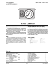

BACK OF
GAUGE
RING
CONNECTOR
(TO GROUND)
POSITIVE WIRE
(TO DASHBOARD
ILLUMINATION WIRE)
S
TEP
6 - A
TTACH
THE
CONTROL
PANEL
TO
THE
DASHBOARD
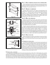
Place the air control panel on the dash where the holes were drilled in Step 1.
Using the provided machine screws, lock nuts, and washers attach the air control
panel to the dashboard or selected mounting surface see Figure "B".
S
TEP
7 - R
OUTE
THE
ELECTRICAL
WIRE
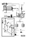
All necessary 16 gage electrical wire and connectors are enclosed with the
kit. Review the electrical schematic before beginning installation see Figure "A".
Cut a length of 16 gage wire that will reach from the positive wire (red) on
the compressor to either white wire on the control panel. Strip 1/4" off each end
of the 16 gage wire and crimp a female spade connector on to each end. Crimp
a male spade connector on to the positive wire (red) from the compressor.
Attach the 16 gage wire to the positive compressor wire by pushing the female
and male spade connectors together. Attach the other end of the 16 gage wire
to either white wire on the control panel in the same manner.
Cut another length of 16 gage wire that will reach from the control panel to
a positive 12 Volt, 20 Amp minimum, ignition activated power source. Strip
1/4" off one end of the 16 gage length and crimp a female spade connector onto
the wire. Attach the wire to the remaining white wire on the control panel by
pushing the male and female spade connectors together. Attach the wire from
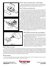
the control panel to the power source using the supplied wire connector. Slide
the wire connector over the existing power wire, then slide the un-stripped
compressor wire into the wire connector. Close the wire connector over both
wires with pliers see Figure "E". Next, install the in-line fuse holder. Cut the
compressor wire near the power source. Insert the un-stripped ends of the wires
into the fuse holder. Use pliers to close the fuse holder over the wires and insert
the 20 Amp blade fuse see Figure "F".
S
TEP
8 - W
IRE
THE
CONTROL
PANEL
FOR
ILLUMINATION
There are two wires (one red and one black) attached to the
gauge on the back of the control panel. Connect the red wire to a
fused dashboard illumination wire. Connect the black wire to a
suitable ground source see Figure "G".
Attach the end of the positive wire to a dashboard illumination
wire using a wire connector. Slip the wire connector over the
existing dashboard illumination wire and insert the un-stripped
gauge panel wire into the wire connector. Close the wire connector
over the wires with pliers see Figure "E". Attach the black wire to
a ground source by crimping a ring connector on to the wire and
securing it to a suitable ground source on the vehicle. Note: Should
additional wire be necessary to reach the dashboard illumination
wire and ground source, use 16 gage multi-strand wire.
S
TEP
9 - C
HECK
THE
SYSTEM
With the Level Command kit and your air helper springs installed, you are ready to test the system. Reattach the negative battery
cable. Turn on the vehicle's ignition. Push the paddle switch up to inflate the air springs. The gauge will display how much air
pressure is in the air springs. Inflate the air helper springs to 70 psi and check the fittings for air leaks with an applied solution of
soap and water. If a leak is detected at a tubing connection, check to make sure that the tube is cut as square as possible and that
it is pushed completely into the fitting. The tubing can easily be removed from the fitting. First, release the pressure from the air
spring. Push the collar towards the body of the fitting and pull out the tube.
S
YSTEM
OPERATION
The Level Command kit allows the air springs to be inflated from the inside of the vehicle. Push the paddle switch up to inflate
the air springs and push the paddle switch down to deflate the air springs.
Figure "G"
WIRE FROM
PANEL LIGHT
CONNECTING WIRE
PLASTIC
CONNECTOR
FUSE HOLDER
FIRESTONE INDUSTRIAL PRODUCTS TELEPHONE: 317-818-8600
12650 HAMILTON CROSSING BOULEVARD 1-800-247-4337
CARMEL, IN 46032 www.ride-rite.com FAX: 317-818-8645
TM
R R