


If you have any questions, call 1-800-54-HOW-TO
BEVEL POINTERS
If the bevel pointers (11) do not indicate zero, loosen the screw that
holds it in place and move the pointer as necessary.
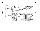
FENCE ADJUSTMENT
Turn Off and Unplug the Miter Saw
In order that the saw can bevel to a full 47 degrees left, the left side of
the fence can be adjusted to the left to provide clearance. To adjust
the fence, loosen the two plastic knobs (7) shown in Figure 1 and
slide the fence to the left. Make a dry run with the saw turned off and
check for clearance. Adjust the fence to be as close to the blade as
practical to provide maximum workpiece support, without interfering
with arm up & down movement. Tighten both knobs securely. When
the bevel operations are complete, don’t forget to relocate the fence to
the right.
NOTE: The guide groove in the left side fence (7) can become
clogged with sawdust. If you notice that it is becoming clogged, use a
stick or some low pressure air to clear the guide groove.
GUARD ACTUATION AND VISIBILITY
The blade guard on your saw has been designed to automatically
raise when the arm is brought down and to lower over the blade when
the arm is raised.
The guard can be raised by hand when installing or removing saw
blades or for inspection of the saw. NEVER RAISE THE BLADE
GUARD MANUALLY UNLESS THE SAW IS TURNED OFF.
NOTE: Certain special cuts will require that you manually raise the
guard. To do this, simply place your right thumb on the upper side of
the guard and roll the guard up just enough to clear the workpiece.
Never tie up or otherwise prevent the guard from operating normally.
The front section of the guard is louvered for visibility while cutting.
the two screws. Pay no attention to the reading of the miter pointer at
this point.
MITER POINTER ADJUSTMENT
Loosen the miter clamp handle (4) and squeeze the miter latch (5) to
move the miter arm to the zero position. With the miter clamp handle
loose allow the miter latch to snap into place as you rotate the miter
arm past zero. Observe the pointer and miter scale (6) through the
miter latch opening. If the pointer does not indicate exactly zero,
loosen screw and re-align the pointer.
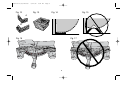
BEVEL STOP ADJUSTMENT
Loosen the bevel clamp knob (10) and move the cutting arm all the
way to the right, then tighten the bevel clamp knob. Using a square,
place one end of the square on the table and the other end against
the blade. Check to see if the blade is at 90 degrees to the table. If an
adjustment is necessary loosen the locknut below the right side bevel
stop (13) and turn the screw until it contacts the casting when the
blade is at 90 degrees. Then tighten locknut. To set the 45 degree
bevel stop (opposite side), first loosen the left side fence clamping
knobs (7) and slide the left side fence as far as it will go to the left.
Loosen bevel clamp knob (10) and move the cutting arm all the way
to the left bevel position and tighten bevel clamp knob. Using a
combination square check to see that blade is at 45 degrees to the
table as shown in Figure 9. If an adjustment is necessary, loosen the
locknut on the left side of the casting and turn screw until it contacts
casting when blade is at 45 degrees. Then tighten locknut.
To achieve 2 degree right bevel or 47 degree left bevel, the stop
screws must be adjusted to allow the arm to move to the desired
location. The bevel stops will need readjustment to the zero and 45
degree positions after cuts are made.
13
395136-00,03,BT1500 6/22/04 9:05 AM Page 13