


AVERTISSEMENT! Lire et comprendre toutes les directives. Le non-respect de toutes
les directives suivantes présente des risques de secousses électriques, d'incendie ou de
blessures graves.
CONSERVER CES MESURES
ZONE DE TRAVAIL
•S'assurer que la zone de travail est propre et bien éclairée. Des établis encombrés et
des endroits sombres présentent des risques d'accidents.
•Ne pas utiliser des outils électriques en présence de vapeurs explosives (comme
celles dégagées par des liquides, des gaz ou des poussières inflammables). Les
étincelles générées par le moteur des outils électriques peuvent enflammer les poussières
ou les vapeurs.
• Éloigner les curieux, les enfants et les visiteurs de la zone de travail lorsqu'on utilise
un outil électrique. Une distraction peut entraîner la perte de maîtrise de l'outil.
MESURES DE SÉCURITÉ RELATIVES À L'ÉLECTRICITÉ
•Les outils à double isolation comportent une fiche polarisée (une lame plus large que
l'autre). La fiche n'entre que d'une façon dans une prise polarisée. Lorsque la fiche
n'entre pas à fond dans la prise, essayer de nouveau après avoir inversé les broches
de la fiche. Si la fiche n'entre toujours pas dans la prise, communiquer avec un
électricien certifié afin de faire installer une prise polarisée. Ne modifier en aucune
GUIDE D’UTILISATION
EXTENSION CORD
When using an extension cord, be sure to use one heavy enough to carry the current your
product will draw. An undersized cord will cause a drop in line voltage resulting in loss of
power and overheating. The table below shows the correct size to use depending on cord
length and nameplate ampere rating. If in doubt, use the next heavier gage. The smaller the
gage number, the heavier the cord.
MOTOR
Your tool is powered by a Black & Decker specified motor. Be sure your power supply agrees
with the nameplate marking. A marking of 120 volts, 50/60 Hz or 120 volts, AC only means that
the tool is designed to operate on normal 120 volt house current. Voltage decrease of more that
10% will cause loss of power and overheating. All Black & Decker tools are factory tested. If
this tool does not run, check the power supply.
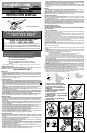
AUXILIARY HANDLE (FIG. 1)
A three position auxiliary handle (5) is furnished with your grinder and can be screwed into
either side of the grinder housing as well as into the top. This handle SHOULD BE USED AT
ALL TIMES to maintain complete control of the tool.
STARTING THE TOOL
To switch your angle grinder on, depress the trigger switch (1). The angle grinder will stop
when the trigger switch is released. For continuous operation depress the lock-on button (2)
while the trigger switch is depressed. Release the trigger switch prior to releasing the lock-
on button. To stop your angle grinder when operation is continuous depress the trigger switch
again and release.
OVERLOAD
Overloading will cause damage to the motor of your angle grinder. This can happen if your
angle grinder is subjected to heavy use for prolonged periods of time. Do not in any circum-
stances, attempt to exert too much pressure on your angle grinder to speed up your work.
The abrasive discs operate more efficiently when light pressure is exerted, thus avoiding a
drop in the speed of your angle grinder.
GRINDING AND WIRE BRUSHING
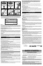
ATTACHING THE WHEEL GUARD (FIG.2)
TURN OFF AND UNPLUG THE TOOL. NEVER GRIND OR BRUSH WITHOUT GUARD IN
PLACE.
Place the angle grinder on a table, spindle up. Align the lug with the slot in the bracket. Press
the guard down and turn it in the direction of the arrow. NOTE: The guard locking pin pre-
vents the guard from coming loose.
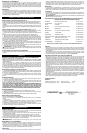
FITTING DEPRESSED CENTER WHEELS (FIGS. 3,4,5,6)
TURN OFF AND UNPLUG THE TOOL. CAUTION: Never use any depressed-center
wheels without the proper guard.
1. Ensure that the guard is fitted properly. Place the inner flange (a) in Fig. 3 on the spindle.
Ensure that it is located on the two flats.
2. Place the grinding wheel on the spindle and inner flange (a) in Fig. 4.
3. Fit the threaded outer flange (b) Fig. 5, making sure it is facing in the correct direction for
the type of wheel fitted. For thick grinding wheels, the flange ( b) is fitted with the raised por-
tion facing towards the wheel. For thin grinding wheels, the flange (b) is fitted with the inner
portion facing away from the wheel.
4. Press in the spindle lock button and rotate the spindle until it locks. Keeping the lock but-
ton pressed in, tighten the outer flange with the spanner wrench provided as shown in Fig. 6.
5. When using a depressed-center wheel, hold the tool so that an angle of approximately
30° exists between the wheel and the work.
WARNING: Check rated speed on depressed-center wheel. Never use a wheel with rated
speed lower than the speed on the nameplate of the tool.
FITTING WIRE CUP BRUSHES
Wire cup brushes screw directly on the spindle of the machine without the use of flanges.
When using wire brushes, thread firmly on spindle by hand.
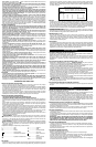
SANDING
REMOVING THE WHEEL GUARD (FIG. 7 SANDING ONLY)
TURN OFF AND UNPLUG THE TOOL.
NOTE: TO PREVENT LOSS OF CONTROL, DO NOT SET TOOL DOWN UNTIL ACCES-
SORY HAS COMPLETELY STOPPED TURNING.
As shown in Fig. 7, place the grinder on a table, spindle up. Rotate the guard in the direction
of the arrow until it stops. Use a small screwdriver to depress the locking pin in the slot. While
holding the locking pin down with the screwdriver, turn the guard slightly in the direction of
the arrow to keep the locking pin depressed. Remove the screwdriver and continue to turn
the guard until it is released.
PRECAUTIONS TO TAKE WHEN SANDING PAINT
1. Sanding of lead based paint is NOT RECOMMENDED due to the difficulty of controlling
the contaminated dust. The greatest danger of lead poisoning is to children and pregnant
women.
2. Since it is difficult to identify whether or not a paint contains lead without a chemical analysis,
we recommend the following precautions when sanding any paint:
PERSONAL SAFETY
1. No children or pregnant women should enter the work area where the paint sanding is being
done until all cleanup is completed.
2. A dustmask or respirator should be worn by all persons entering the work area. The filter
should be replaced daily or whenever the wearer has difficulty breathing.
Minimum Gage for Cord Sets
Volts Total Length of Cord in Feet
120V 0-25 26-50 51-100 101-150
240V 0-50 51-100 101-200 201-300
Ampere Rating
More Not more American Wire Gage
Than Than
0-6 18 16 16 14
6 - 10 18 16 14 12
10 - 12 16 16 14 12
12 - 16 14 12 Not Recommended
NOTE: ONLY THOSE DUSTMASKS SUITABLE FOR WORKING WITH LEAD PAINT
DUST AND FUMES SHOULD BE USED. ORDINARY PAINTING MASKS DO NOT
OFFER THIS PROTECTION. SEE YOUR LOCAL HARDWARE DEALER FOR THE
NIOSH APPROVED PROPER MASK.
ENVIRONMENTAL SAFETY
1. Paint should be removed in such a manner as to minimize the amount of dust gener-
ated.
2. Areas where paint removal is occurring should be sealed with plastic sheeting of 4
mils thickness.
3. Sanding should be done in a manner to reduce tracking of paint dust outside the work
area.
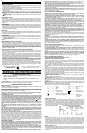
FITTING ABRASIVE DISCS
TURN OFF AND UNPLUG THE TOOL.
Use an abrasive disc with a backing pad for sanding with your angle grinder.
1. Remove the guard.
2. Place the flange, (backing pad and abrasive disc sold separately) and outer flange on
the spindle as shown in Figure 8. Figure 8A shows how to attach an abrasive disc with a
rubber backing pad.
3. Tighten the abrasive disc as shown in Figure 9 by depressing the spindle lock button
and turning the abrasive disc by hand.
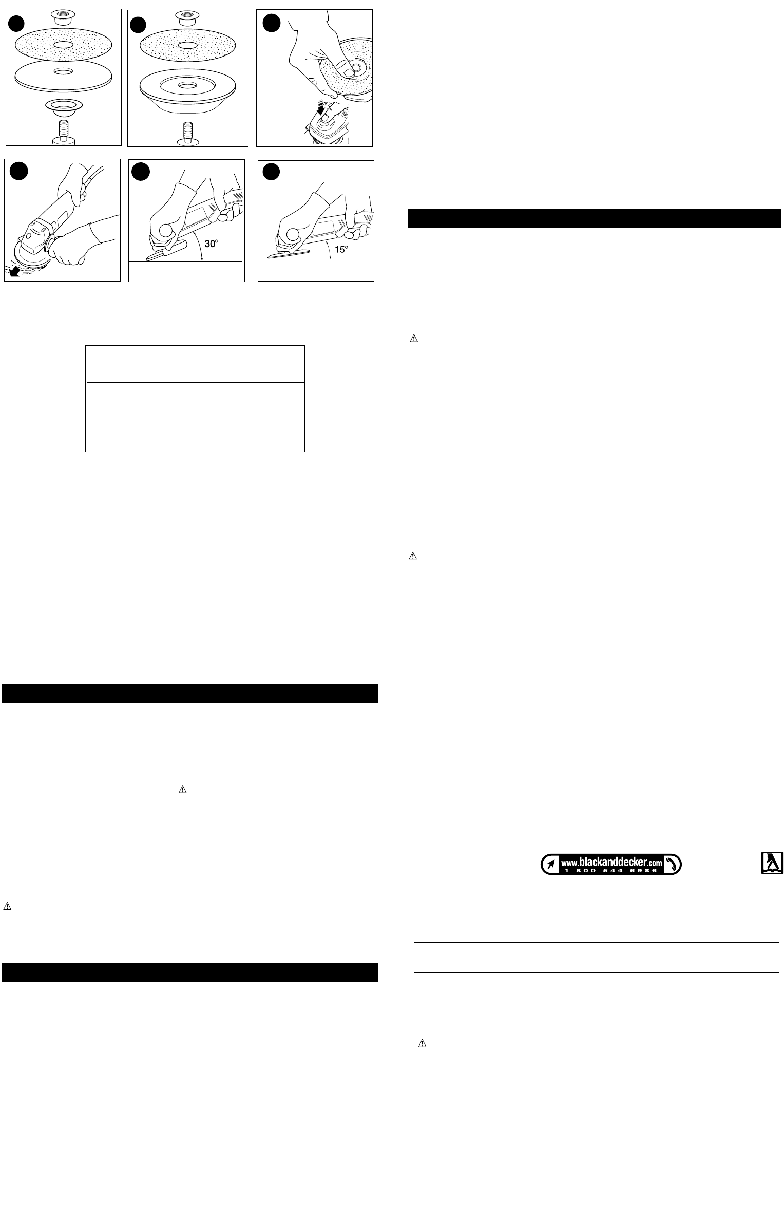
GENERAL INFORMATION
HELPFUL HINTS
• Hold your angle grinder with one hand on the body and the other hand firmly around the
side handle as shown in Figure 10.
• Always position the guard so that as much of the exposed disc as possible is pointing away
from you.
• Be prepared for a stream of sparks when the disc touches the metal.
• Maintain an angle between the disc and work surface (Fig. 11) of approximately 30° when
grinding and 10°-15° when sanding ( Fig. 12) for best tool control, material removal, and
minimal loading.
WARNING: Always wear eye protection while operating this power tool.
TOOL MAINTENANCE
CLEANING: Blowing dust and grit out of the motor housing using compressed air is a
necessary maintenance procedure. Dust and grit containing particles from metal grinding
often accumulate on interior surfaces and could create an electrical shock hazard if not
cleaned out.
LUBRICATION
Black & Decker tools are properly lubricated at the factory and are ready for use. Tools
should be lubricated regularly every year depending on usage. (Tools used on heavy duty
jobs and tools exposed to heat may require more frequent lubrication.) This lubrication
should be attempted only by trained power tool repairperson's such as those at Black &
Decker service centers or in other qualified service personnel.
IMPORTANT
To assure product SAFETY and RELIABILITY, repairs, maintenance and adjustments
should be performed by Black & Decker service centers or other qualified service personnel,
always using Black & Decker replacement parts.
ACCESSORIES
Recommended accessories for use with your tool are available from your local dealer or
authorized service center. If you need assistance regarding accessories, please call: 1-800-
54-HOW-TO (544-6986).
WARNING: The use of any accessory not recommended for use with this tool could be
hazardous.
SERVICE INFORMATION
Black & Decker offers a full network of company-owned and authorized service locations
throughout North America. All Black & Decker Service Centers are staffed with trained
personnel to provide customers with efficient and reliable power tool service.
Whether you need technical advice, repair, or genuine factory replacement parts, contact
the Black & Decker location nearest you. To find your local service location, refer to the
yellow page directory under "Tools—Electric" or call: 1-800-54-HOW TO.
FULL TWO-YEAR HOME USE WARRANTY
Black & Decker (U.S.) Inc. warrants this product for two years against any defects in material
or workmanship. The defective product will be replaced or repaired at no charge in either of
two ways.
The first, which will result in exchanges only, is to return the product to the retailer from
whom it was purchased (provided that the store is a participating retailer). Returns should be
made within the time period of the retailer’s policy for exchanges (usually 30 to 90 days after
the sale). Proof of purchase may be required. Please check with the retailer for their specific
return policy regarding returns that are beyond the time set for exchanges.
The second option is to take or send the product (prepaid) to a Black & Decker owned or
authorized Service Center for repair or replacement at our option. Proof of purchase may be
required. Black & Decker owned and authorized Service Centers are listed under "Tools-
Electric" in the yellow pages of the phone directory.
This warranty does not apply to accessories. This warranty gives you specific legal rights
and you may have other rights which vary from province to province. Should you have any
questions, contact the manager of your nearest Black & Decker Service Center. This
product is not intended for commercial use. FREE WARNING LABEL REPLACEMENT: If
your warning labels become illegible or are missing, call 1-800-544-6986 for a free
replacement.
RENSEIGNEMENTS À RETENIR
• Attendre que la meule atteigne sa vitesse maximale avant de la poser sur l'ouvrage.
• Tenir la meuleuse à l'angle approprié, tel qu'illustré à la fig.11, fig. 12.
10
11
12
8
9
8A
See ‘Tools-Electric’
– Yellow Pages –
for Service & Sales
Imported by
Black & Decker (U.S.) Inc.,
701 E. Joppa Rd.
Towson, MD 21286 U.S.A.