


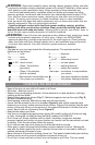
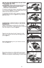
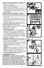
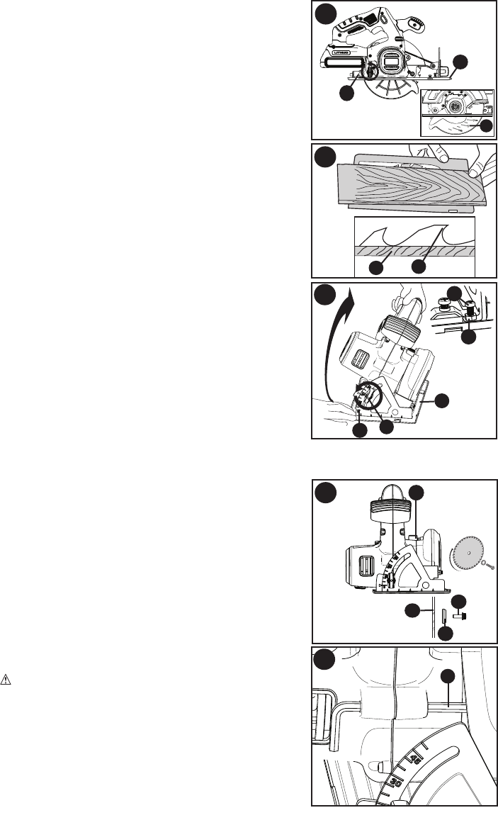
CUTTING DEPTH ADJUSTMENT - FIGURES I & J
The depth of cut should be set according to the
thickness of the workpiece.
Loosen the depth adjustment knob (11) to unlock the
saw shoe (5) as shown in figure I.
Move the saw shoe into the desired position. The
corresponding depth of cut can be read from the scale (14).
of the blade projects below the workpiece (16) as
shown in figure J.
Tighten the knob to lock the saw shoe in place.
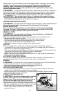
BEVEL ANGLE ADJUSTMENT - FIGURE K
This tool can be set to bevel angles between 0° and 50°.
saw shoe (5).
corresponding bevel angle can be read from the scale (17).
saw shoe in place.
bevel angle of an actual cut on a scrap piece of material.
SHOE ADJUSTMENT FOR 90° CUTS
The shoe (5) has been set by the factory to assure that
the blade is perpendicular to the shoe at 0° bevel setting.
against the blade (7) and shoe (5) to adjust the 90° setting.
screw (18b) (inset figure K) so that the shoe will
stop at the proper angle. Retighten jam nut against
the shoe while holding adjustment screw in position.
scrap piece of material.
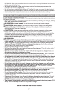
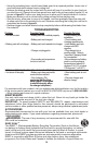
ATTACHING AND REMOVING THE BLADE - FIGURE L - M
washer (19) as shown in figure L.
bolt (20) with the blade wrench (9) until the blade lock
engages and the blade stops rotating.
NOTE: Blade wrench is stored on the saw as shown
in figure M.
NOTE:
clockwise. To tighten, turn counterclockwise.
NOTE: Never engage the blade lock while the saw is
running, or engage in an effort to stop the tool. Never
turn the tool on while the blade lock is engaged.
Serious damage to your saw will result.
LOWER BLADE GUARD
WARNING: Laceration Hazard. The lower
blade guard is a safety feature which reduces the
risk of serious personal injury. Never use the saw if
the lower guard is missing, damaged, mis-
assembled or not working properly. Do not rely on
the lower blade guard to protect you under all
circumstances. Your safety depends on following
all warnings and precautions as well as proper
operation of the saw. Check lower guard for proper
closing before each use as outlined in Additional
12
L
20
19
7
13
M
9
K
17
5
10
18b
18a
J
15
16
I
5
11
14