


15
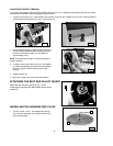
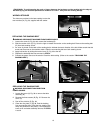
Two holes are provided in the base casting to store the
two wrenches (A) Fig. 33, supplied with the sander.
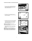
WARNING: To avoid trapping the work or fingers between the backstop and the sanding belt, the edge of
the table (A) Fig. 32 should be positioned a maximum of 1/16 in. away from the sanding belt (B).
WRENCH STORAGE
Fig. 33
A
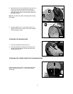
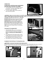
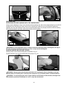
REPLACING THE SANDING BELT
WARNING: DISCONNECT MACHINE FROM POWER SOURCE.
1. Loosen the screw (A) Fig. 34 and remove the backstop (B).
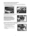
2. Slide the tension lever (C) Fig. 35 to the right to release the tension on the sanding belt. Remove the sanding belt
(D) from both sanding drums.
3. An arrow is printed on the back of the sanding belt to indicate the travel direction of the belt. Make certain that this
arrow and the arrow on the machine match. Slide the new sanding belt over both sanding drums.
4. Apply belt tension by sliding the tension lever (C) Fig. 35 to the left.
5. Replace the backstop that was removed in STEP 2.
6. Connect the power source to the sander. Check the belt tracking. (Refer to the section "TRACKING THE
SANDING BELT").
Fig. 34
A
Fig. 35
B
D
C
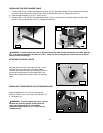
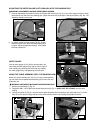
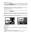
REPLACING THE SANDING DISC
WARNING: DISCONNECT MACHINE FROM
POWER SOURCE.
1. Loosen the screw (A) Fig. 36 to remove the table
assembly (B).
2. Remove the three screws (B) Fig. 37. Remove the
cover (D).
4. Peel off the old disc (E) Fig. 38.
5. Clean the disc plate (F) Fig 38. Peel the backing
from new sanding disc. Press the new sanding disc
firmly into position on disc plate (F) and replace the
lower cover and table assembly removed in STEPS
1 and 2.
A
B
Fig. 36