


Conductor size (mm2) Cable rating (Amperes)
0.75 6
1.00 10
1.50 15
2.50 20
4.00 25
Cable length (m) 7.5 15 25 30 45 60
Voltage Amperes Cable rating (Amperes)
120V~ 0 - 2.0 6 6 6 6 6 10
2.1 - 3.4 6 6 6 6 15 15
3.5 - 5.0 6 6 10 15 20 20
5.1 - 7.0 10 10 15 20 20 25
7.1 -12.0 15 15 20 25 25 -
12.1 -20.0 20 20 25 - - -
220V~ 0 - 2.0 6 6 6 6 6 6
2.1 - 3.4 6 6 6 6 6 6
3.5 - 5.0 6 6 6 6 10 15
5.1 - 7.0 10 10 10 10 15 15
7.1 -12.0 15 15 15 15 20 20
12.1 -20.0 20 20 20 20 25 -
Assembly and adjustment
Prior to assembly and adjustment always
unplug the tool.
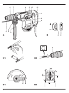
Inserting and removing SDS-max® accessories
(fig. C1 & C2)
This machine uses SDS-max® drill bits and chisels
(refer to the inset in fig. C2 for a cross-section of an
SDS-max® bit shank).
• Clean and grease the bit shank.
Only apply a slight amount of lubricant to the
bit shank. Do not apply lubricant to the
machine.
• Insert the bit shank into the tool holder (6), and press
and turn the bit slightly until the sleeve snaps into
position.
• Pull on the bit to check if it is properly locked. The
hammering function requires the bit to be able to
move axially several centimetres when locked in the
tool holder.
•To remove a bit pull back the tool holder locking
sleeve (6) and pull the bit out of the tool holder.
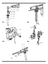
Selecting the operating mode (fig. D1 & D2)
The tool can be used in two operating modes (fig. D1):
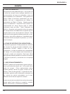
Hammer drilling: for concrete and masonry
drilling operations.
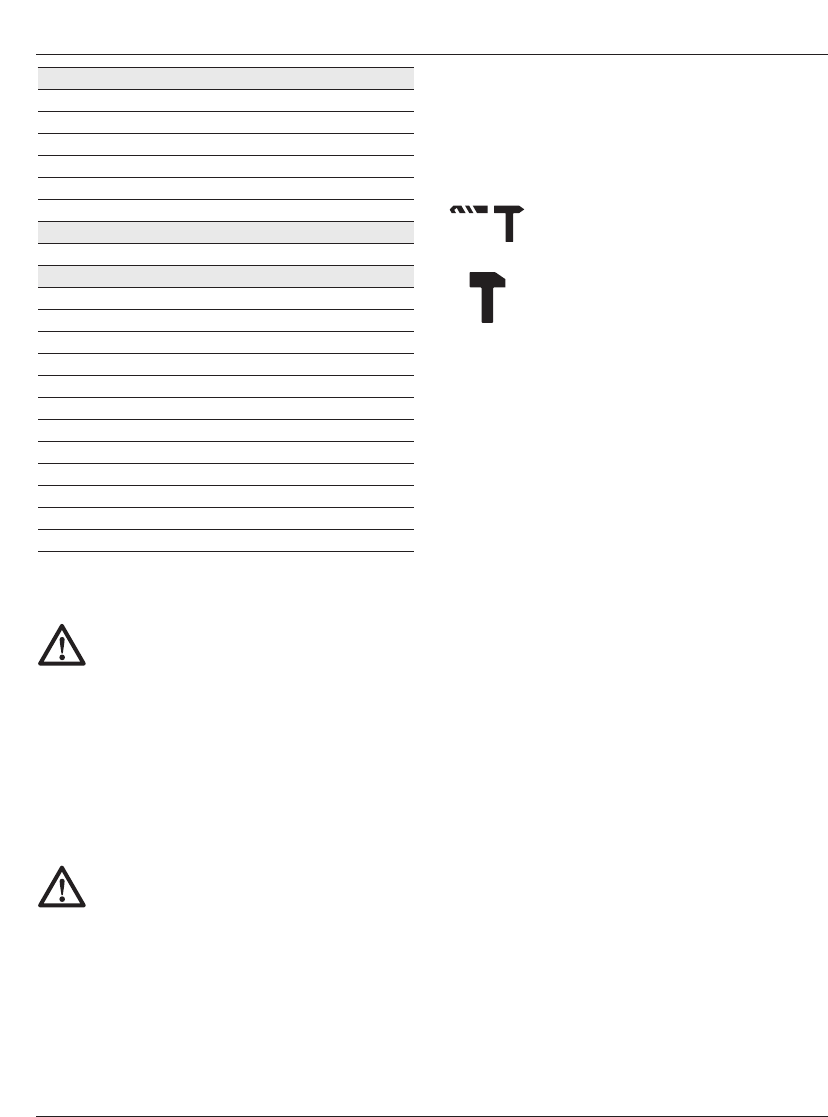
Hammering only: for light chipping, chis-
elling and demolition applications. In this
mode the tool can also be used as a lever
to free a jammed drill bit.
•To select the operating mode, press the safety lock
(5) and rotate the mode selector switch (4) until it is
points to the symbol of the required mode.
•Release the safety lock and check that the mode
selector switch is locked in place.
Indexing the chisel position
The chisel can be indexed and locked into 8 different
positions (fig. D2).
• Rotate the mode selector switch (4) until it points
upward.
• Rotate the chisel in the desired position.
• Set the mode selector switch (4) to the “hammering
only” position.
•Twist the chisel until it locks in position.
Setting the electronic speed and impact control
dial (fig. B)
•Turn the dial (2) to the desired level. The higher the
number, the greater the speed and impact energy.
With dial settings from “1” (low) to “5” (full power) the
tool is extremely versatile and adaptable for many
different applications. The required setting is a matter
of experience. E.g.:
- when chiselling or drilling in soft, brittle materials or
when minimum break-out is required, set the dial to
“1” or “2” (low);
- when breaking or drilling in harder materials, set the
dial to “5” (full power).
D25600
With dial settings from “1” to “7” the tool allows a fur-
ther fine-adjustment to the choice of application.
ENGLISH
7