


MOTOR
Be sure your power supply agrees with the nameplate marking. 120 Volts, 60Hz means alter-
nating current only should be used to operate this tool.A power decrease of more than 10%
will cause loss of power and overheating. All Black and Decker tools are factory tested; if this
tool does not operate, check the power supply.
BENCH MOUNTING
1. The grinder should be unplugged.
2. Position grinder on workbench. Check for the availability of power for the grinder. Mark
location of holes for drilling.
3. Drill appropriate sized holes.
4. Insert 1/4” (6mm) Hex head bolts through washers and the holes. You may want to use
washers on the underside of the bench as well.
5. Tighten the nuts. Do not overtighten. Allow the rubber feet to absorb the vibration when
the grinder is running.
Assembly
Note: Approximate assembly time is 30 minutes. Tools Required: 10mm and 12mm
wrenches or adjustable wrench.
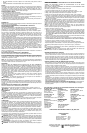
INSTALLING SPARK GUARDS, LIGHT FIXTURES, EYE SHIELDS AND QUENCH TRAY
TURN OFF TOOL AND DISCONNECT FROM POWER SUPPLY
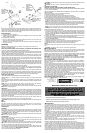
There are seven seperate hardware bags and a quench tray packed with your bench grinder.
Hardware bag #’s 1,2, 3 and 4 shown in Figure 2 are used to assemble the spark guard, light
fixture and eye shield assemblies shown in Figure 3.
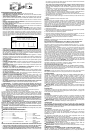
To begin assembly insert the 1/2” long machine screw with washer through the slot of the left
side spark guard and into the threaded hole located at the top of the inner metal wheel guard.
Adjust the edge of the spark guard to within 1/16” of the grinding wheel or other accessory.
Tighten the screw securely. Continue to adjust spark guard to be within 1/16” of grinding
wheel or other accessory as wear occurs.
Align the left side spark guard with the opening below the left side light fixture. Next, align the
clear plastic eye shield (rib side up per Figure 3) with the left side spark guard. With the three
items aligned, insert the 3-1/2” bolt through them from the left side insuring that the square
portion of the bolt head is seated fully into the square eye shield recess. Place a knob and
washer onto the threaded end of the bolt and hand tighten.
Adjust the eye shields so they are between the wheels and your eyes. Tighten the shields in
place by tightening the plastic knob in the assembly by hand. NOTE: EYE SHIELDS ARE
NOT DESIGNED TO REPLACE SAFETY GLASSES.
Repeat the procedure for the right side assembly inserting the 3-1/2” bolt from the right side.
A quench tray is included for use in cooling the workpiece after the grinding process. The tray
can be filled with water (only use water) and attached to either side of the grinder by aligning
the tabs on the side of the tray with the slots on the outer sides of the wheel guards.
INSTALLING TOOL RESTS
TURN OFF POWER AND DISCONNECT FROM POWER SUPPLY.
Hardware bags 5, 6, 7, and the remaining two knobs from bag #1 are used to assemble the
tool rests.
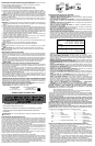
First install the left side tool rest brackets, as shown in Fig. 4. Next attach the tool rests. Use
the bolts, washers, spacers and lock nuts from the plastic bag to secure the brackets and tool
rests in place.
NOTE: There is a left and right tool rest. When in actual use, the tool rests should be
adjusted to within 1/8” of the grinding wheel or other accessory being used.
CAUTION: Use the washers and screws supplied. Longer screws may interfere with the
movement of the grinding wheel.
OPERATION
NEVER USE A BENCH GRINDER IF IT IS NOT FIRMLY FASTENED TO A WORK BENCH
OR RIGID FRAME. Before turning the grinder on, put on safety glasses. Turn on the grinder
and allow it to reach full speed (3500 RPM ). Hold the workpiece firmly and against the tool
rest. Hold very small pieces with pliers or other suitable clamps. Feed the work smoothly and
evenly into the grinding wheel. Move the work slowly and avoid jamming the work against the
wheel. As the wheel tends to slow down you should occasionally release the pressure to let
the wheel return to full speed.
Grind only on the face of the grinding wheel and never on the side. (Some wheels are
designed for side grinding and will say so on their instruction sheets).
CAUTION: Prolonged grinding will cause most materials to become hot. Handle them with
pliers.
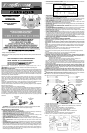
SWITCH
The switch is located on the front of the grinder, on the base. (Figure 1) To turn the tool on
depress the side of the rocker switch on the right side, marked “I”. To turn off the grinder,
depress the left side of the rocker switch, marked “O”.
MAINTENANCE
CLEANING
Blowing dust and grit out of the wheel guards using compressed air is a necessary regular
maintenance procedure. Dust and grit containing metal particles often accumulate on interi-
or surfaces and could create an electrical shock hazard if not frequently cleaned out.
ALWAYS WEAR SAFETY GLASSES.
CAUTION: Never use solvents or other harsh chemicals for cleaning the non-metallic parts
of the tool. Use clean, dry rag only.
ACCESSORIES
Recommended accessories for use with your tool are available at extra cost from your dis-
tributor or local service center.
Grinding wheels must fit within the confines of the guard and must be rated higher than the
recommended speed as marked on the nameplate.
CAUTION: Strands of wire brushes may break and fly off while in use. Users and others
in the area should wear adequate eye, face and body protection. Use only wire brushes that
are rated at or greater than the RPM shown on the tool’s nameplate.
The use of wire brushes is only recommended with the use of a spacer, Black & Decker part
no. 791695-00. The spacer should be positioned behind the inner clamp washer toward the
motor. To order the spacer call 1-800-54-HOW-TO (544-6986).
Do not use the spacer with grinding wheels.
WARNING: To reduce the risk of injury, always use proper guards when grinding and wear
eye protection.
CAUTION: The use of any non-recommended accessory may be hazardous.
CHANGING ACCESSORIES
TURN OFF THE TOOL AND DISCONNECT FROM POWER SUPPLY.
CHANGE ACCESSORIES WHEN THE SPARK GUARD CAN NO LONGER BE ADJUSTED
TO 1/16” FROM THE WHEEL.
USE ONLY WHEELS THAT MEASURE 6” IN DIAMETER. THIS TOOL HAS 1/2” ARBORS
ON BOTH SIDES.
Follow the steps below to remove and replace an accessory.
1.Raise the eye shield up, and out of the way.
2.Loosen and pull the tool rest out as far as possible. Do not remove it.
3.Loosen and pull the spark guard out as far as possible, Do not remove it.
4.Remove the five screws from the side of the wheel cover and remove the cover.
5.Insert a flat bladed screwdriver into the slot in the left end of the grinder’s rotor shaft. Hold the
screwdriver firmly to keep the shaft from turning as you loosen and remove the hex nut in the
center of the grinding wheel or other accessory.
NOTE: If you are changing only the right side accessory, you need not remove the left wheel
cover. A hole in the center of the cover permits screwdriver insertion into the slotted shaft.
Unscrew the nut in the center of the grinding wheel. It may be necessary to strike the wrench
sharply in the loosening direction with the heel of your hand to loosen the nut.
NOTE: The nut on the right side of the grinder has a standard right hand thread (turn
counterclockwise to loosen). The one on the left side has a left hand thread (turn clockwise to
loosen).
6.Remove the wheel washer and the wheel.
7. Inspect the wheel for cracks, chips or any other visible damage (other than normal wear)
and discard if such damage is found. Inspect the blotters for damage. If the blotters are
missing or severely damaged, replace them with pieces of thin cardboard or blotter paper cut
in the same shape. NEVER USE A GRINDING WHEEL WITHOUT A BLOTTER ON EACH
SIDE OF THE WHEEL.
8.Install the new wheel or other accessory. Be sure that both wheel washers are in place
(concave sides toward wheel). Use only flanges furnished with the grinder.
9. Hold as before and tighten the nut firmly but do not overtighten. OVERTIGHTENING CAN
CRACK A GRINDING WHEEL.
10. Replace the wheel cover and its five screws.
11. Adjust the spark guard to 1/16" (1.6mm) from the accessory and tighten it securely.
12. Adjust the tool rest to 1/8" (3.2mm) from the accessory and tighten securely.
13. Adjust the eye shield to a point between your eyes and the accessory.
LIGHT
To replace the bulb, remove the screw and bulb housing shown in Figure 3 and unscrew the
bulb.
CAUTION: To reduce the risk of fire, use 10 watt max. appliance bulb.
SERVICE INFORMATION
Black & Decker offers a full network of company-owned and authorized service locations
throughout North America. All Black & Decker Service Centers are staffed with trained
personnel to provide customers with efficient and reliable power tool service.
Whether you need technical advice, repair, or genuine factory replacement parts, contact the
Black & Decker location nearest you. To find your local service location, refer to the yellow
pages directory under "Tools—Electric" or call: 1-800-54-HOW-TO (544-6986).
IMPORTANT: To assure product SAFETY and RELIABILITY, repairs, maintenance and adjust-
ment should be performed by authorized service centers or other qualified service organiza-
tions, always using identical replacement parts.
FULL TWO-YEAR HOME USE WARRANTY
Black & Decker (U.S.) Inc. warrants this product for two years against any defects in
material or workmanship. The defective product will be replaced or repaired at no charge in
either of two ways.
The first, which will result in exchanges only, is to return the product to the retailer from whom
it was purchased (provided that the store is a participating retailer). Returns should be made
within the time period of the retailer’s policy for exchanges (usually 30 to 90 days after the
sale). Proof of purchase may be required. Please check with the retailer for their specific
return policy regarding returns that are beyond the time set for exchanges.
The second option is to take or send the product (prepaid) to a Black & Decker owned or
authorized Service Center for repair or replacement at our option. Proof of purchase may be
required. Black & Decker owned and authorized Service Centers are listed under
"Tools-Electric" in the yellow pages of the phone directory.
This warranty does not apply to accessories. This warranty gives you specific legal rights and
you may have other rights which vary from state to state. Should you have any questions,
contact the manager of your nearest Black & Decker Service Center.
This product is not intended for commercial use.
FREE WARNING LABEL REPLACEMENT: If your warning labels become illegible or are
missing, call 1-800-544-6986 for a free replacement.
See ‘Tools-Electric’
– Yellow Pages –
for Service & Sales
Imported by
Black & Decker (U.S.) Inc.,
701 E. Joppa Rd.
Towson, MD 21286 U.S.A.
Mise à la terre
En cas de mauvais fonctionnement ou de bris de l’outil, la mise à la terre procure un chemin
de moindre résistance au courant électrique afin de minimiser les risques de secousses
électriques. Le cordon de l’outil comporte un conducteur de terre et une fiche de mise à la
terre. La fiche doit être branchée dans une prise de machine bien installée et mise à la terre
conformément aux lois et règlements locaux. Ne pas modifier la fiche fournie. Lorsque la
fiche n’entre pas dans la prise, demander à un électricien qualifié d’installer une prise
appropriée.
La mauvaise connexion du conducteur de terre de l’outil présente des risques de secouss-
es électriques. Le conducteur dont l’isolant est vert ou vert avec des lignes jaunes constitue
la mise à la terre. En cas de réparation ou de remplacement du cordon ou de la fiche, ne
pas relier le conducteur de terre à une borne sous tension.
Consulter un électricien qualifié ou le personnel des centres de service an cas
d’incompréhension des instructions relatives à la mise à la terre ou en cas de doute quant
à la mise à la terre de l’outil.
Utiliser seulement des cordons de rallonge trifilaires dotés de fiche mise à la terre à trois
broches, ainsi que des prises à 3 orifices acceptant la fiche de l’outil.
Réparer ou remplacer immédiatement les cordons endommagés ou usés.
L ‘outil est conçu pour être branché sur un circuit dont les prises ressemblent à celle
illustrée à la figure A. L’outil comporte une fiche de terre qui ressemble à celle illustrée à la
figure A. On peut se servir d’un adaptateur temporaire (comme celui des figures B et C) pour
brancher la fiche dans une prise à 2 orifices (fig. B) lorsqu’il n’y a pas de prise mise à la terre.
Il faut seulement se servir de l’adaptateur temporaire jusqu’à ce qu’un électricien certifié
puisse installer une prise mise à la terre appropriée. Il faut alors relier l’oreille rigide, la cosse
ou tout autre objet du genre de couleur verte à une mise à la terre permanente (comme à
la boîte d’une prise bien mise à la terre).
AA
AA
VV
VV
AA
AA
NN
NN
TT
TT
DD
DD
EE
EE
RR
RR
EE
EE
TT
TT
OO
OO
UU
UU
RR
RR
NN
NN
EE
EE
RR
RR
LL
LL
EE
EE
PP
PP
RR
RR
OO
OO
DD
DD
UU
UU
II
II
TT
TT
PP
PP
OO
OO
UU
UU
RR
RR
QQ
QQ
UU
UU
EE
EE
LL
LL
QQ
QQ
UU
UU
EE
EE
RR
RR
AA
AA
II
II
SS
SS
OO
OO
NN
NN
QQ
QQ
UU
UU
EE
EE
CC
CC
EE
EE
SS
SS
OO
OO
II
II
TT
TT
,,
,,
CC
CC
OO
OO
MM
MM
PP
PP
OO
OO
SS
SS
EE
EE
RR
RR
LL
LL
EE
EE
11
11
88
88
00
00
00
00
55
55
44
44
44
44
--
--
66
66
99
99
88
88
66
66
IMPORTANTS RENSEIGNEMENTS:
• Toujours porter des lunettes de protection.
• S’assurer que les appuis, les pare-étincelles et les protège-yeux soient
solidement fixés avant de faire fonctionner l’outil.
FIG. 3
SPARK GUARD
PARE-
ÉTINCELLES
GUARDACHIS-
PAS
EYE SHIELD
PROTÈGE-YEUX
PANTALLA
PROTECTORA
DE OJOS
FIG. 4
TOOL REST
FERRURE DE
L’APPUI
RECEPTACULO
PARA EL
SOPORTE DE LA
HERRAMIENTA
TOOL REST BRACKET
APPUI DE L’OUTIL
SOPORTE DE LA HER-
RAMIENTA
MEULEUSE D’ÉTABLI DE 152 mm (6 po)