


ENGLISH
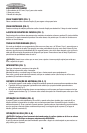
DEPTH STOP (FIG. 1)
Depth stop is set at the factory for a new 14" wheel to prevent wheel from cutting into the supporting surface.
To allow more depth of cut, use the flat wrench provided (G) to loosen the depth stop bolt (M) and raise bolt to
desired height and then turn jam nut (M) clockwise until seated firmly on the casting. Securely tighten the
depth stop bolt before use.
CAUTION: When changing to a new wheel, readjust depth stop to original position to prevent cutting into
supporting surface.
TRIGGER SWITCH (FIG. 1)
To start the tool, depress the trigger switch (N). To turn the tool off, release the trigger switch. Keep hands and
material from wheel until it has coasted to a stop.
To prevent unauthorized use of tool, install a standard padlock (not included) into the padlock hole (O) located in
the trigger.
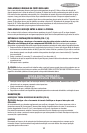
MATERIAL CLAMPING AND SUPPORTING (FIG. 2, 3)
• Angles are best clamped and cut with both legs resting against base.
• A spacer block slightly narrower than the workpiece can be used to increase wheel utilization (Fig. 2).
• Long workpieces must be supported by a block so it will be level with top of base (Fig. 3). The cut off end
should be free to fall downward to avoid wheel binding.
VISE OPERATION (FIG. 4)
The vise (F) has a quick-travel feature. To release the vise when it is clamped tightly, turn the crank (H) counter-
clockwise one or two times to remove clamping pressure. Lift vise lever (I) up. Pull crank assembly out as far as
desired. Vise may be pushed forward into work without cranking. Lower vise lever (I) then tighten vise (F) on
work by using crank (H).
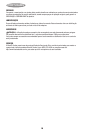
FENCE OPERATION (FIG. 5, 6)
CAUTION: Turn off and unplug the tool before making any adjustments or removing or installing
attachments or accessories. Be sure the trigger switch is in the OFF position. The fence (E) can be ad-
justed two ways: to change desired cutting angle and to change spacing between the fence and vise.
TO CHANGE THE DESIRED CUTTING ANGLE
Use the wrench provided to loosen (do not remove) the two fence bolts (P). Align the desired angle indicator line with the
slot line (Q) in the base (D). Securely tighten both fence bolts before use. For more accurate square cuts, disconnect the
power supply, loosen the two fence bolts, push arm down until wheel extends into base. Place a square against the
wheel and adjust fence against the square. Securely tighten both fence bolts before use. When making a miter cut, the
vise (F) may not clamp securely, depending on the thickness of the workpiece and the miter angle. Other aids (such as
spring, bar or C-clamps) will be necessary to secure the workpiece to the fence when making these cuts.
TO CHANGE SPACING BETWEEN THE FENCE AND VISE
Using the wrench provided, loosen and remove the two fence bolts (P). Adjust the fence (E) to desired locations.
Insert both fence bolts in provided locations. Securely tighten both fence bolts before use.
REMOVAL AND INSTALLATION OF WHEELS (FIG. 7, 8)
CAUTION: Turn off and unplug the tool before making any adjustments or removing or installing
attachments or accessories. Be sure the trigger switch is in the OFF position. Do not make any
adjustment while the wheel is in motion.
Do not make any adjustment while chop saw is plugged into power supply.
1. Push in wheel lock lever (L) and rotate wheel (J) by hand until wheel lock lever engages slot in inside flange
(R) to lock wheel. Loosen the bolt (S) counterclockwise in the center of the abrasive wheel with the included
flat wrench. (G). Bolt has right-hand thread.
2. Remove the bolt (S), washer (T), outside flange (U) and old wheel (J).
3. Make sure flange surfaces are clean and flat. Install the new abrasive wheel by reversing the above steps.
4. Do not overtighten bolt.
24