


6
Labels on tools
Electrical safety
This tool is double insulated; therefore no earth
wire is required. Always check that the power
supply corresponds to the voltage on the rating
plate.
If the supply cord is damaged, it must be replaced by the
manufacturer or an authorised Black & Decker Service
Centre in order to avoid a hazard.
Features
1. Lock-on button
2. Variable speed on/off switch
3. Blade storage compartment cover
4. Shoe plate locking lever
5. Shoe plate
6. Blade support roller
7. Tool-free blade clamp
Assembly
Warning! Before attempting any of the following operations,
make sure that the tool is switched off and unplugged and
that the saw blade has stopped. Used saw blades may be
hot.
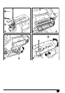
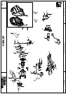
Fitting the saw blade (fig. A)
Hold the saw blade (8) as shown, with the teeth facing
forward.
Push and hold the blade clamp (7) down.
Insert the shank of the saw blade into the blade holder
(9) as far as it will go.
Release the blade clamp (7).
Saw blade storage (fig. B)
Saw blades (8) can be stored in the storage compartment
located on the side of the tool.
Open the cover (3) of the saw blade storage
compartment by holding the tab on the top of the cover
(3) and pulling it outward.
The blades are retained in the compartment by a
magnetic strip. To remove a blade, press down on one
end of the blade to raise the other end, and remove.
Close the cover (3) of the saw blade storage
compartment and make sure that it is latched closed.
Warning! Close the compartment door securely before
operating the saw.
Residual risks
Additional residual risks may arise when using the tool which
may not be included in the enclosed safety warnings. These
risks can arise from misuse, prolonged use etc.
Even with the application of the relevant safety regulations
and the implementation of safety devices, certain residual
risks cannot be avoided. These include:
Injuries caused by touching any rotating/moving parts.
Injuries caused when changing any parts, blades or
accessories.
Injuries caused by prolonged use of a tool. When using
any tool for prolonged periods make sure you take
regular breaks.
Impairment of hearing.
Health hazards caused by breathing dust developed
when using your tool (example:- working with wood,
especially oak, beech and MDF).
Use
Adjusting the shoe plate for bevel cuts (fig. C and D)
Warning! Never use the tool when the shoe plate is loose or
removed.
The shoe plate (5) can be set to a left or right bevel angle of
up to 45°.
Pull the shoe plate locking lever (4) outwards to unlock
the shoe plate (5) from the 0 degree position (fig. D).
Pull the shoe plate (5) forward and set the required
bevel 15°, 30° and 45° indicated in the bevel angle
window.
Push the shoe plate locking lever (4) back towards the
saw to lock the shoe plate (5).
To reset the shoe plate (5) for straight cuts:
Pull the shoe plate locking lever (4) outwards to unlock
the shoe plate (5).
Set the shoe plate (5) to an angle of 0° and push the
shoe plate backwards.
Push the shoe plate locking lever (4) back towards the
saw to lock the shoe plate (5).
Switching on and off
To switch the tool on, press the variable speed on/off
switch (2).
To switch the tool off, release the variable speed on/off
switch (2).
For continuous operation, press the lock-on button (1)
and release the on/off switch (2).
To switch the tool off when in continuous operation,
press the on/off switch (2) and release it.
Warning! To reduce the risk of injury, the user
must read the instruction manual.