8 9
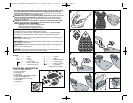
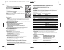
Fitting a Sanding Sheet Onto a Contour Sanding Piece (Fig. 8)
• Align the sanding sheet with the contour sanding piece.
• Press the sanding sheet onto the contour sanding piece, making
sure that the sanding sheet follows the shape of the profile.
Maintenance
Use only mild soap and damp cloth to clean the tool. Never let any liquid get inside the tool;
never immerse any part of the tool into a liquid.
IMPORTANT: To assure product SAFETY and RELIABILITY, repairs, maintenance and
adjustment should be performed by authorized service centers or other qualified service
organizations, always using identical replacement parts.
Accessories
Look for the following Mouse
TM
accessories at your local retailer.
Catalog # Description Contents
74-583 120 Medium Sandpaper 5 sheets
74-584 180 Fine Sandpaper 5 sheets
74-585 220 Extra Fine Sandpaper 5 sheets
74-586 Sandpaper Assortment 1 sheet of 120 grit paper, 2 sheets each 180,
220 paper
74-587 Finger Attachment Paper 5 fingers each of 120, 180, 220
74-588 1 OT Power Wool 3 sheets
74-589 4 OT Power Wool 3 sheets
74-581 Polishing Kit 2 sheets of 1 OT power wool, 2 sheets of 4 OT
power wool, 2 foam pads
74-582 Scrubbing Kit 2 coarse abrasive pads, 2 fine abrasive pads,
2 foam pads
74-580 Sanding/Polishing Kit 2 sheets of 1 OT power wool, 2 sheets of 180
grit sandpaper, 2 sheets of 240 grit sandpaper,
2 foam pads, 5 finger attachment paper
74-671 Universal Sandpaper/Coarse 5 sheets of 80 grit
74-672 Universal Sandpaper/Med. 5 sheets of 120 grit
74-673 Universal Sandpaper/Fine 5 sheets of 220 grit
74-674 Universal Sandpaper Assortment
Recommended accessories for use with your tool are available at extra cost. Listings per
retailer may vary. The hook and loop pad and individual bases are replaceable parts. If
they become worn, contact your local service center. For more information call:
1-800-544-6986.
WARNING: The use of any accessory not recommended for use with this tool could be
hazardous.
Application / Accessory Matrix
ACCESSORY RECOMMENDED APPLICATIONS / USES
MEDIUM GRIT SANDPAPER PAINT, VARNISH, RUST REMOVAL
FINE GRIT SANDPAPER SURFACE BLENDING AND FINISHING
EXTRA FINE GRIT SANDPAPER SANDING BETWEEN COATS OF PAINT OR VARNISH
DETAIL SANDING TIPS CORNERS / HARD TO REACH PLACES
1 OT POLISHING / STRIPPING WOOL POLISHING METALS / STRIPPING VARNISH OR URETHANE
4 OT FINE POLISHING WOOL FINE POLISHING, SATIN FINISH ON PAINT / VARNISH / URETHANE
GREY FOAM PAD APPLYING AND REMOVING POLISH
WHITE NON
-WOVEN PAD LIGHT SCRUBBING
RED NON-WOVEN PAD HEAVY SCRUBBING / RUST REMOVAL
The pads described above are available in kits where Mouse products are sold, The hook
and loop pad and individual bases are replaceable parts. If they become worn, contact
your local service center. For more information call 1-800-544-6986.
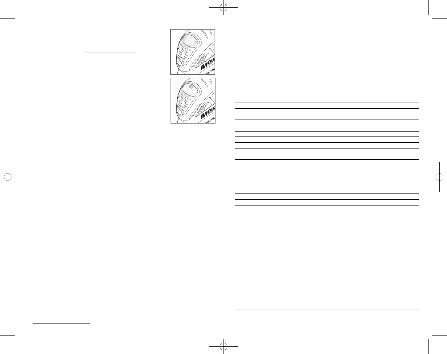
ZONE 2
Displays when:
• Optimum pressure is being applied to achieve optimum
performance and low fatigue.
Zone Lens will illuminate a high intensity green light
which will
appear all across the Zone Indicator (“U” display).
ZONE 3
Displays when:
• Too much pressure is being applied.
Zone Lens will illuminate a red light
which will appear in the center
of the Zone Indicator (“U” display).
NOTE: Excessive pressure may result in harming or causing divots
in the surface you are sanding.
Detail Sanding
WARNING: Always unplug product from power supply before any of the following
operations.
Your tool is equipped with a teardrop base which allows you to use it on large flat
surfaces and tight spots or corners.
The pad tips may wear unevenly, depending on use. The pads are designed to allow you to
interchange and /or rotate the diamond tip.
Fitting Sanding Sheets ( Fig. 2)
• Detach the two diamond-shaped tips from the sanding sheet.
• Hold the tool with the sanding base facing upwards.
• Place the sanding sheet onto the sanding base.
The diamond-shaped tip can be reversed and replaced when worn.
• When the front part of the tip is worn, detach it from the sheet, reverse it and press it onto
the sanding base again.
• When the whole tip is worn, remove it from the sanding base and fit a new tip.
Tip of the Sanding Base ( Fig. 3)
When the sanding base tip is worn, it can be reversed or replaced.
• Reverse or replace the worn part.
Finger Attachment ( Fig. 4)
The finger attachment is used for fine detail sanding.
• Remove the screw.
• Remove the diamond-shaped tip holder from the sanding base.
• Fit the finger attachment onto the sanding base.
• Fit and tighten the screw.
• Align the sanding sheet with the finger attachment.
Contour Holder Attachment (Fig. 5)
• The contour sanding pieces are for sanding curved surfaces and grooves.
• Remove the screw.
• Remove the diamond-shaped tip holder from the sanding base.
• Fit the contour holder onto the sanding base.
• Fit and tighten the screw.
Fitting and Removing a Contour Piece (Fig. 6 & 7)
• Choose the contour sanding piece profile most suitable for your application.
• Place one end of the contour sanding piece into the recess at the front end of the contour
holder.
• Push the other end of the contour sanding piece until it clicks into place.
• T
o remove the contour sanding piece, push it forward then pull the rear end out of
the contour holder (fig. 7).
90518305 03 MS600 ZONE MOUSE:??????-00 BDL500 laser 12/11/09 10:51 AM Page 8


