


8
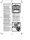
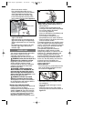
BEVEL ANGLE ADJUSTMENT
Adjust bevel angle (figure 7) using bevel
adjustment knob and bevel scale. Tighten
knob securely.
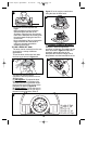
ATTACHING AND REMOVING THE BLADE
NOTE: The first time the blade bolt is
removed from saw without a blade
installed, it may be necessary to place
the blade wrench on the bolt head and
tap it sharply in the counter clockwise
direction.
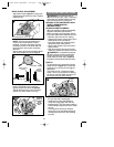
Retract lower guard and assemble blade
and clamp washer as shown (Fig. 8).
Insure large surface of washer is toward
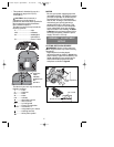
blade. Use spindle lock to prevent
spindle rotation as shown in figure 9.
Tighten blade securely. Never engage
spindle lock while blade is turning.
OPERATING INSTRUCTIONS
WARNING: To reduce the risk of
serious personal injury, read, understand
and follow all important safety warnings
and instructions prior to using tool.
GENERAL CUTS (IMPORTANT: READ
SAFETY WARNINGS AND
INSTRUCTIONS. )
GUARD AGAINST KICKBACK
With unit unplugged, follow all assembly,
adjustment and set up instructions.
Make sure lower guard operates. Select
the proper blade for the material to be cut.
• Measure and mark work for cutting.
• Support and secure work properly (See
Safety Rules and Instructions).
• Use appropriate and required safety
equipment (See Safety Rules).
• Secure and maintain work area (See
Safety Rules).
• With plug inserted and guard closed,
make sure switch turns saw on and off.
WARNING: It is important to support
the work properly and to hold the saw
firmly to prevent loss of control which
could cause personal injury. Figure 3
illustrates recommended hand position.
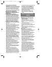
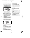
SWITCH
To operate the tool, depress the trigger
switch shown in figure 10. The tool will
continue to run as long as the trigger is
depressed.
To turn the tool off, release the trigger
switch. There is no provision for locking
the tool on, and the switch should never
be locked on by any other means.
KERF PLATE ADJUSTMENT
• Be sure the saw is unplugged.
• Install laser module and actuate to
verify laser edge aligns with the kerf
indicator edge. (This is a factory setting.)
• If this setting is aligned the saw is ready
for use.
• If the alignment has been affected
during use or the saw blade has been
changed please perform the following
process.
8
Blade
Outer clamp
washer
Saw
spindle
Blade clamping screw
Inner
clamp
washer
Direction of teeth
10
Trigger
Switch
Bevel adjustment knob
7
Spindle lock
Dispositif de
verrouillage de
l’arbre
Seguro de la
flecha
9
633145-02,01 QP1020LK 12/16/05 1:20 PM Page 8