


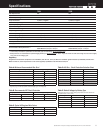

Specifications are subject to change. See bluesea.com/P12 for current information.
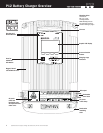
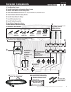
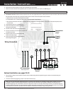
1. AC Wire (see Table D page 5)
NOTE: Wire length must reach from the panel to the battery charger AC Connections with proper routing, support, drip loops, service loops, and termination.
NOTE: Yellow is preferred for negative however diagrams are drawn in black for visibility.
3. Fuse holders for connection to each battery. (see Table B page 5)
4. Fuses for fuse holders. (see Table B page 5)
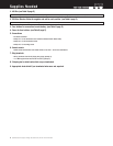
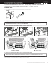
5. Screwdrivers
• Flat blade screwdriver
• Phillips #1 – for AC Termination cover and DC Termination Strain Relief clamp
• Phillips #2 – for AC termination screws
• Phillips #3 – for mounting screws
6. Socket wrench
• 10mm socket with extension and ratchet handle or nut driver – for DC wire terminations
7. Ring terminals
• #8 ring terminals sized for AC/Supply wire gauge (quantity 3)
• ¼” or M6 ring terminals sized for DC wire sizes (quantity 4)
8. Crimping tool or obtain wires that are pre-terminated
9. Appropriate heat shrink if pre-terminated wires were not acquired
2. DC Wire: Black or Yellow for negative and red for each positive. (see Table A page 5)
Supplies Needed
8
P12
7521 AND 7522 BATTERY CHARGERS