


6 en FPE-1000-SLC
F.01U.078.099 | 5.0 | 2011.11 Bosch Security Systems, Inc.
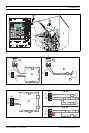
module carefully into position along the guide rails (refer to Figure 1,
Page 4, Item 1)
2. Ensure that the connections seat into the slot properly (refer to
Figure 1, Page 4, Item 2).
3. Press down softly until the snap-fit hook locks into place (refer to
Figure 1, Page 4, Item 3).
4. Connect the earth ground wire to the ground blade terminal on the
right side of the mainboard (refer to Figure 1, Page 4, Item 4).
To remove a plug-in module, press the snap-fit hook carefully from left to
right and pull the board toward the panel front.
Wiring
General Wiring Guidelines
Electrical energy from one wire can transfer to another wire producing
induced noise which can interfere with telephone communication or cause
false alarms. To avoid induced noise, follow these guidelines:
- Keep input wiring away from high current output and power wiring. Pull
separate cables for high-voltage circuits, phone line circuits, Option
bus, Notification Appliance circuits, Signaling Line circuits, and relay
circuits.
- Pull wires from different groups through separate conduits. If you must
run them together, do so for as short a distance as possible or use
shielded cable. Connect the shield to earth ground at the panel. High
and low voltage circuits must be separated.
- Route wiring around not across the circuit board. Wiring proximity to
the circuit board could induce noise into sensitive electronic elements
or pick up unwanted RF noise from the high speed circuits.
- High frequency noise, such as that produced by the inductive reactance
of a speaker or bell, can be reduced by running the wire through ferrite
shield beads or by wrapping the wire around a ferrite toroid.
Signaling Line Circuit Wiring
The Signaling Line Circuit connects to analog addressable devices.
Refer to the FPA-1000 Installation and Operation Guide (P/N F.01U.173.607)
for:
- listing of compatible devices
- detailed wiring style requirements.
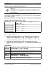
Signaling Line Circuits may be wired as Class A Style 6 or 7 or Class B
Style 4 circuits. Class A configuration is recommended because this allows
the system to poll the circuit in both directions, ensuring circuit operation in
the event of a single break in the wiring.
The Signaling Line Circuit is power-limited and supervised.
No special wire is required for addressable loops. The wire can be
untwisted, unshielded, solid or stranded as long as it meets the National
Electric Code 760-51 requirements for power-limited fire protective signaling
cables.