


-7-
Operating Instructions
TRIGGER CONTROLLED VARIABLE SPEED
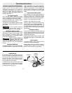
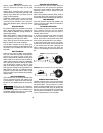
Your tool is equipped with a variable speed
trigger switch. The tool speed can be
controlled from minimum to maximum
nameplate rated RPM by the pressure you
apply to the trigger. Apply more pressure to
increase the speed and release pressure to
decrease speed (Fig. 1).
"LOCK-ON" BUTTON
The "Lock-ON" button, located in the handle
of your tool allows for continuous operation at
maximum RPM without holding the trigger.
TO LOCK TRIGGER "ON": squeeze trigger,
depress button and release trigger.
TO UNLOCK THE TRIGGER: squeeze trigger
and release it without depressing the "Lock-
ON" button.
If the “Lock-ON” button is
continuously being de-
pressed, the trigger can not be released.
REVERSING SWITCH LEVER
The reversing lever is located above the trigger
switch and is used to reverse rotation of the
bit. To use drill in “Forward” rotation move
lever to left side of tool. For “Reverse” rotation
move lever to right side of tool.
Do not change direction of
rotation until the tool
comes to a complete stop. Shifting during
rotation of the chuck can cause damage to
the tool.
VARIABLE SPEED DIAL
This feature enables you to preset the trigger
at desired speeds by rotating the dial on the
trigger. Regardless of the pressure applied on
trigger, the tool will not operate any faster than
maximum preset speed. You can change the
preset maximum speed simply by rotating the
adjusting dial to a higher or lower speed
setting.
GEAR CHANGE SELECTION
Gear selection: The proper gear selection is
directly related to the speed and torque
required for various jobs. The following should
be adhered to when selecting the proper gear:
Speed 1 = low speed with high torque
Speed 2 = high speed with low torque
Changing gears: Change gear position only
with the motor at a complete standstill. To
change gears rotate the gear selection lever. If
you have difficulties changing from one gear to
the other, turn the chuck by hand until the
gears engage.
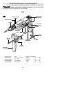
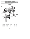
AUXILIARY HANDLE
The auxiliary handle will provide additional
control, support and guidance for the drill. The
handle is adjustable to any position around the
360˚ handle collar mount.
Installing side handle: Slide the handle over
the handle collar mount. Securely tighten wing
knob (A).
DEPTH GAUGE
Your drilling depth can be pre-set and/or
repeated by using the depth gauge.
Setting depth: After the auxiliary handle is
installed, slide the depth gauge to desired
depth and securely tighten wing knob (B).
!
WARNING
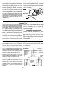
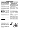
INSERTING BIT
For small bits, open jaws enough to insert the
bit up to the flutes. For large bits, insert the bit
as far as it will go. Center the bit as you close
the jaws by hand. This positions the bit
properly, giving maximum contact between
the chuck jaws and the bit shank.
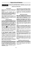
To tighten chuck, insert key into each of the
three key holes in succession and tighten
clockwise firmly. The chuck can be released
by using one hole only (Fig. 2).
!
CAUTION
FIG. 2
Clockwise
Counter
Clockwise