


7
3. Insert three fourths of shank of accessory
into the collet, and securely tighten with the
wrench provided.
Removing Accessories
Repeat steps 1 and 2 of above and remove
accessory.
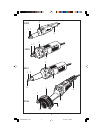
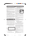
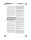
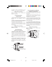
Guard Installation (Model 1214 only)
1. Loosen guard mounting strap nuts 10, and the
wing nuts 7 on guard cover 8.
2. Place wheel guard 9 over spindle and positon
guard mounting strap on lip of the machined
spindle housing.
3. Rotate guard 9 into position where maximum
protection is provided for the operator from
spark and debris, then tighten mounting strap
nuts 10.
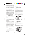
Installing Grinding Wheel
( Model 1214 only)
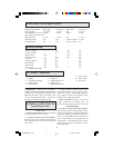
Your tool uses grinding wheels 5" maximum
diameter by 1" thick.
1. Insert the locking pin into the hole in the inner
flange 11 to prevent the spindle shaft from
rotating.
2. Hold locking pin in place and rotate nut 13
counter-clockwise with an open end wrench
and remove nut 13 and outer flange 12.
Start the tool before applying to work and let the
tool come to full speed before contacting the
workpiece. Lift the tool from the work before
releasing the switch. DO NOT turn the switch
“ON” and “OFF” while the tool is under load;
this will greatly decrease the switch life.
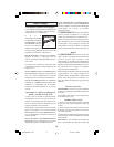
Grinding Wheels
WARNING! Before using a grinding wheel,
be certain that its maximum safe operating
speed is not exceeded by the nameplate speed
of the grinder. Do not exceed the recommended
wheel diameter.
Grinding wheels should be carefully selected
in order to use the grinder most efficiently.
Wheels vary in type of abrasive, bond, hardness,
grit size and structure. The correct type of
wheel to use is determined by the job.
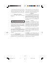
Installing Accessories
CAUTION! Be sure that the diameter of the
shank is the same size as the inside diameter of
the collet.
Models 1209, 1210 & 1215 are equipped with
a 1/4" collet.
(Models 1209 & 1215)
1. Place the (22mm) spindle lock wrench that is
provided onto the spindle to prevent the spindle
from rotating.
2. Hold wrench in place and rotate collet nut 1
counter-clockwise with the (14mm) wrench
that is provided.
3. Insert three fourths of shank of accessory
into the collet, and securely tighten with the
wrench provided.
NOTE: When replacing collets on the model
1215, loosen the collet nut and remove together
with collet 6, then screw in new collet.
Removing Accessories
Repeat steps 1 and 2 of above and remove
accessory.
Installing Accessories
(Model 1210)
1. Insert the locking pin provided into hole in
the spindle, to prevent the spindle from rotating.
2. Hold locking pin in place and rotate collet nut
1 counter-clockwise with the (14mm) wrench
that is provided.
11
10
9
13
12
GRINDING
WHEEL
7
8
BM 3609929341 12/03 12/16/03, 11:40 AM7