


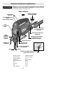
CHIP BLOWER
Your jigsaw is equipped with a two position
chip blower to help keep the cutting line
clear of chips.
By adjusting the chip blower lever the force
of the discharge air may be altered as
follows;
BLOWER SWITCHED ON
For working with wood, plastic
and similar materials that produce
large amounts of sawdust.
BLOWER SWITCHED OFF
For working with metals and when
cooling agents are used, or with
dust collection accessory.
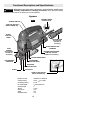
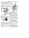
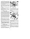
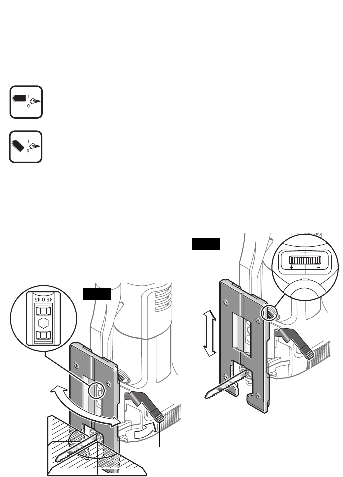
FOOTPLATE ANGLE ADJUSTMENT
The footplate may be tilted to allow angle
cuts up to 45º in either direction (Fig. 10).
To adjust footplate, remove dust shroud if
used, open footplate lock lever and slide the
footplate slightly forward towards the front
of tool, then rotate to desired angle (Fig. 10).
Note: If the footplate cannot be adjusted or
you have difficulty after the footplate lock
lever has been released, rotate tension wheel
in the “-” direction (Fig. 11).
The detent slots will hold the footplate firmly
at 45º, and there are additional position
marks for 15º, 22.5º and 30º angles.
Intermediate angles may be set with a
protractor (Fig. 10).
After positioning the footplate close the
footplate lock lever to securely tighten the
footplate adjustment (Fig. 10).
Note: If the lock lever does not securely
tighten the footplate after the lever is closed,
open lock lever and rotate the tension wheel
in the “+” direction until desired tension has
been achieved (Fig. 11).
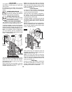
FLUSH CUTTING
To allow the saw to make a perpendicular
cut close to a vertical surface, the footplate
may be repositioned as follows.
Note that when the footplate is retracted in
this manner, only 90º cuts are possible, and
the optional cutting guide and anti-splinter
insert guide may not be used.
To adjust footplate, remove dust shroud and
anti-splinter insert, open footplate lock lever
move the footplate back in the 0º alignment
slot (Fig. 11).
Note: If the footplate cannot be adjusted or
you have difficulty after the footplate lock
lever has been released, rotate tension wheel
in the “-” direction (Fig.11).
After positioning the footplate close the
footplate lock lever to securely tighten the
footplate adjustment (Fig. 11).
Note: If the lock lever does not securely
tighten the footplate after the lever is closed,
open lock lever and rotate the tension wheel
in the “+” direction until desired tension has
been achieved (Fig. 11).
TOOL TIPS
Always be certain that smaller workpieces
are securely fastened to a bench or other
support. Larger panels may be held in place
by clamps on a bench or sawhorses.
-10-
FOOTPLATE
LOCK LEVER
FIG. 10
FIG. 11
FOOTPLATE
LOCK LEVER
TENSION
WHEEL
BEVEL
SCALE