


-9-
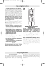
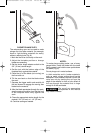
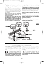
FOOTPLATE ADJUSTMENT
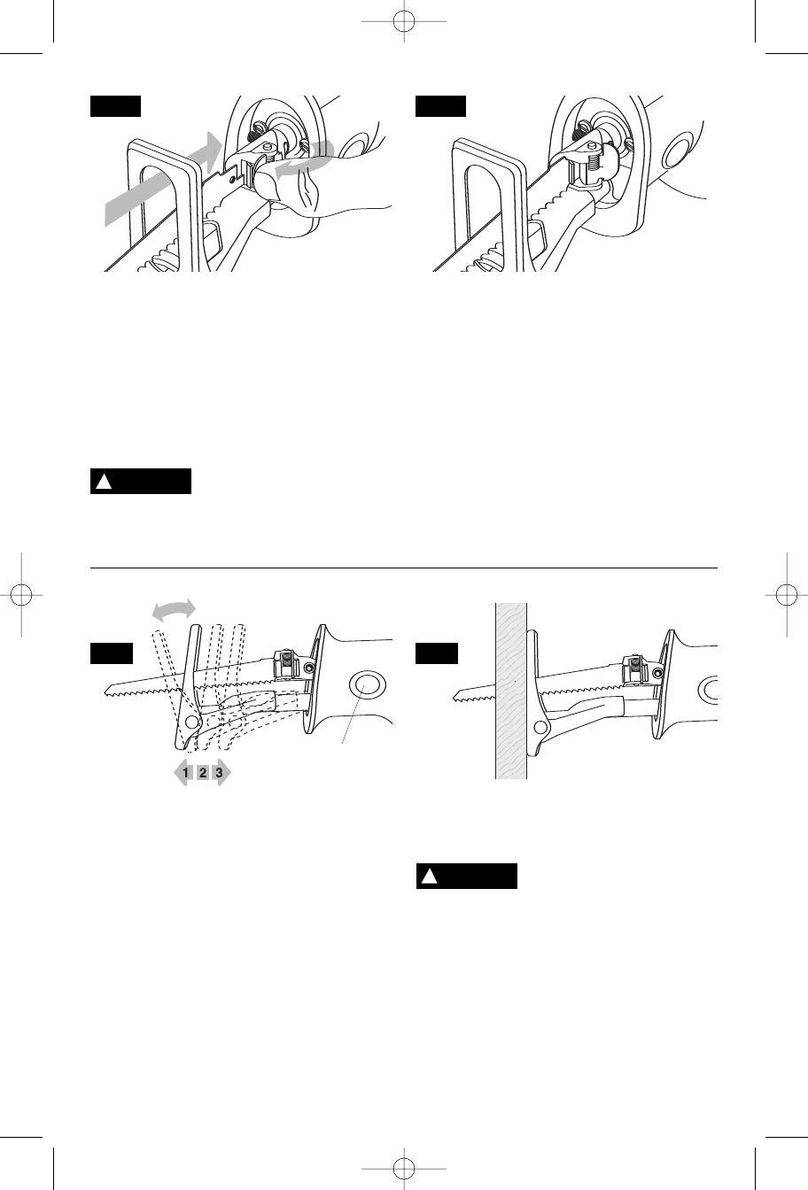
The footplate tilts in order to keep as much of
its surface in contact with the work surface
Fig. 5 (a).
The footplate assembly can also be locked
into one of three projection positions to
optimize blade life and/or to reduce blade
protrusion beyond the end of the footplate,
such as when cutting into large diameter pipe
or into walls. To adjust the footplate position,
simply push the footplate release button and
move the footplate into the desired position.
The locking mechanism is spring-loaded to
lock into one of the 3 positions on the footplate
assembly. If the footplate is pulled out so far
that a notch shows at the other end of the
shaft, the footplate assembly is extended too
far out, and must be retracted to the one of
the 3 positions Fig. 5 (b).
Do not push the footplate
release button while sawing.
It will cause the footplate to release from the
desired settings and you may lose control and
be injured.
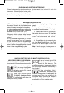
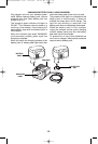
To reduce the risk of injury, be sure the blade
extends beyond the footplate and all the way
through the workpiece throughout the stroke.
Blades may shatter if the blade hits the
footplate or hits the work at an angle that is
nearly head-on (Fig. 6).
FIG. 3
FIG. 5
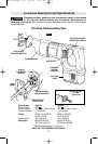
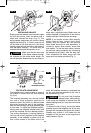
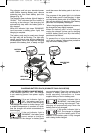
INSTALLING A BLADE
Simply press the release lever forward to open
the tool-less clamp; insert the blade until it
stops and release the lever (Fig. 3). The
spring-loaded mechanism will lock the clamp
against the blade (Fig. 4). Push in and pull out
on the blade to be sure the pin in the clamp
housing goes through the hole in the blade to
hold the blade securely. The blade may be
inserted with the teeth facing down or up.
Make sure that the front end
of the blade extends through
the footplate for the entire stroke length. Do
not use specialty blades that are very short or
those with a significant cant. Blade must not
contact footplate. A blade which is too short or
canted could jam inside the foot and snap.
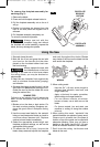
NOTE: If you require a basic (Allen wrench)
blade clamp for any reason (extra thick
blades, very thin blades, etc.) an optional
basic blade clamp kit is sold separately. It
contains a clamp, Allen wrench, screw and
lock washer. To use the basic clamp, remove
the tool-less clamp assembly by unscrewing
the setscrew that holds it onto the draw bar.
Then assemble the basic clamp with the
screw and lock washer provided (Fig. 1).
!
WARNING
!
WARNING
FIG. 6
FIG. 4
FOOTPLATE
RELEASE BUTTON
(a)
(b)
BM 2610925947 6-05 6/10/05 10:35 AM Page 9