


REMOVING CHUCK
Rotate the clutch ring to the drill bit
symbol “ ”. Open the chuck all the way,
remove left-hand thread screw inside chuck
by turning it clockwise (Fig. 4).
Insert the short arm of a 1/2" hex key wrench
and close jaws on flats of wrench (Fig. 5).
Strike long arm of wrench sharply
counterclockwise, remove wrench and
unthread chuck from spindle.
INSTALLING CHUCK
Always keep the spindle threads, the threads
of the chuck and securing screw free of
debris. To install a chuck, reverse “removing
the chuck” procedure.
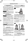
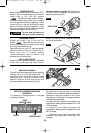
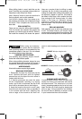
BATTERY CHARGED CONDITION
INDICATOR
The battery is equipped with a charged
condition indicator.
By pressing the button ON, the charged
condition can be checked when the battery is
removed or when the machine is not in use.
After approx. 5 seconds, the charged indicator
switches off automatically.
• • •
When all three lights are illuminated, this
indicates the battery pack is between 67% and
100% charged.
• • When only two lights illuminate, this
indicates the battery pack is between 33% and
66% charged.
• When only one light illuminates, this
indicates the battery pack is less than 33%
charged.
FIG. 5
-10-
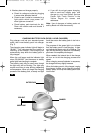
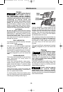
INSERTING BITS
Move reverse switch lever to the center “OFF”
p
osition. Remove battery pack and rotate the
c
lutch ring to the drill bit symbol
“ ”. Rotate the chuck sleeve counter-
clockwise viewing from chuck end, and open
chuck to approximate drill bit diameter. Insert
a clean bit up to the drill bit flutes for small
bits, or as far as it will go for large bits. Close
chuck by rotating the chuck sleeve clockwise
and securely tighten by hand (Fig. 4).
Do not use the power of
the drill while grasping
chuck to loosen or tighten bit.
Friction burn
or hand injury is possible if attempting to
g
rasp the spinning chuck.
!
WARNING
CHUCK SLEEVE
FIG. 4
BUTTON
GREEN
INDICATOR LIGHTS
RED
INDICATOR LIGHT
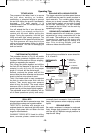
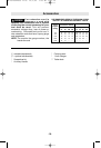
AUXILIARY HANDLE
The tool must be supported with the auxiliary
handle, which can be swiveled 360˚. To
reposition and/or swivel the handle, loosen
the hand grip, move the handle to the
desired position along the barrel and
securely retighten the hand grip (Fig. 6).
FIG. 6
BM 2610944508 11-06 12/1/06 3:29 PM Page 10