


P
age 17
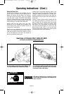
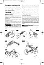
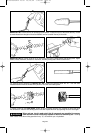
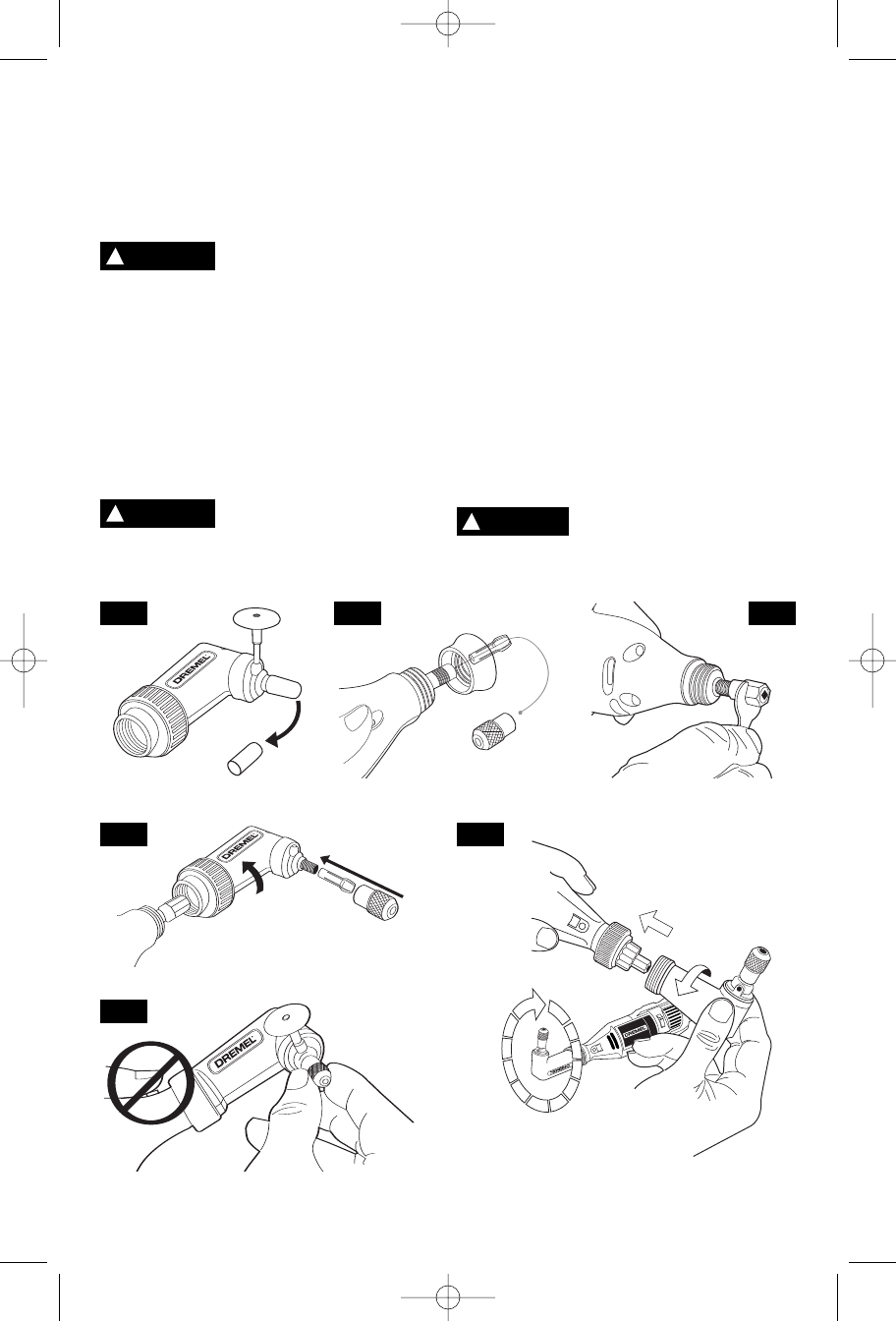
Right Angle Attachment 575
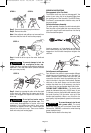
Before you begin, remove the black protective cap on
your attachment. If cap does not slide off easily, insert
the shank portion of any accessory through the
housing opening of the attachment to hold shaft from
rotating. Then twist off. Figure 1.
Do not use the rotary tool shaft
lock button when changing
accessories on the attachment. Internal damage to
the attachment may occur.
Remove the housing cap from your existing rotary
tool as shown in fig. 2. Then press the shaft lock
button on your rotary tool, unscrew the collet nut and
remove the collet.
Set your collet nut and collet aside it will be
reinstalled later in step 4.
Install the drive adapter, included with your right
angle attachment, on the motor shaft as shown in
fig.3 and tighten.
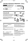
Do not over tighten drive
adapter. Tighten the drive adapter
finger tight and then tighten an additional 1/3 turn
with the wrench. (Wrench included with your rotary
tool kit)
Screw the attachment onto your rotary tool. Hand
tighten only. Reassemble the collet and the collet nut
from step 2, on to the output shaft of the attachment.
Figure 4.
The right angle attachment can be oriented on your
rotary tool in 12 different positions. The attachment
should be positioned so the on/off speed control
switch is easy to access.
To reposition, unscrew the collar from the attachment
until disengaged. Slide the attachment off. Then,
reposition, slide the attachment back on the tool and
retighten the collar. Figure 5.
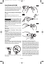
To change an accessory, insert the shank portion of
any accessory (3,2 mm recommended) through the
housing opening of the attachment to hold the shaft
from rotating. With the shaft secured, loosen the
collet nut and insert an accessory as deeply as
possible to avoid wobble during use. You may need to
pull back the shank from the housing opening to
provide clearance while inserting the accessory.
Figure 6.
Attachment can become hot after
prolong usage.
1
2
3
4
5
CAUTION
!
CAUTION
!
FIG. 1 FIG. 2 FIG. 3
FIG. 4 FIG. 5
FIG. 6
!
WARNING
DM 2610925474 10-04 10/19/04 3:40 PM Page 17