


-12-
!
Before attaching a backing
pad be sure its maximum safe
operating speed is not exceeded by the
nameplate speed of the tool.
Wheel guard may not be used
for most sanding operations.
Always reinstall wheel guard when converting
back to grinding operations.
Disconnect battery pack from tool.
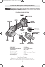
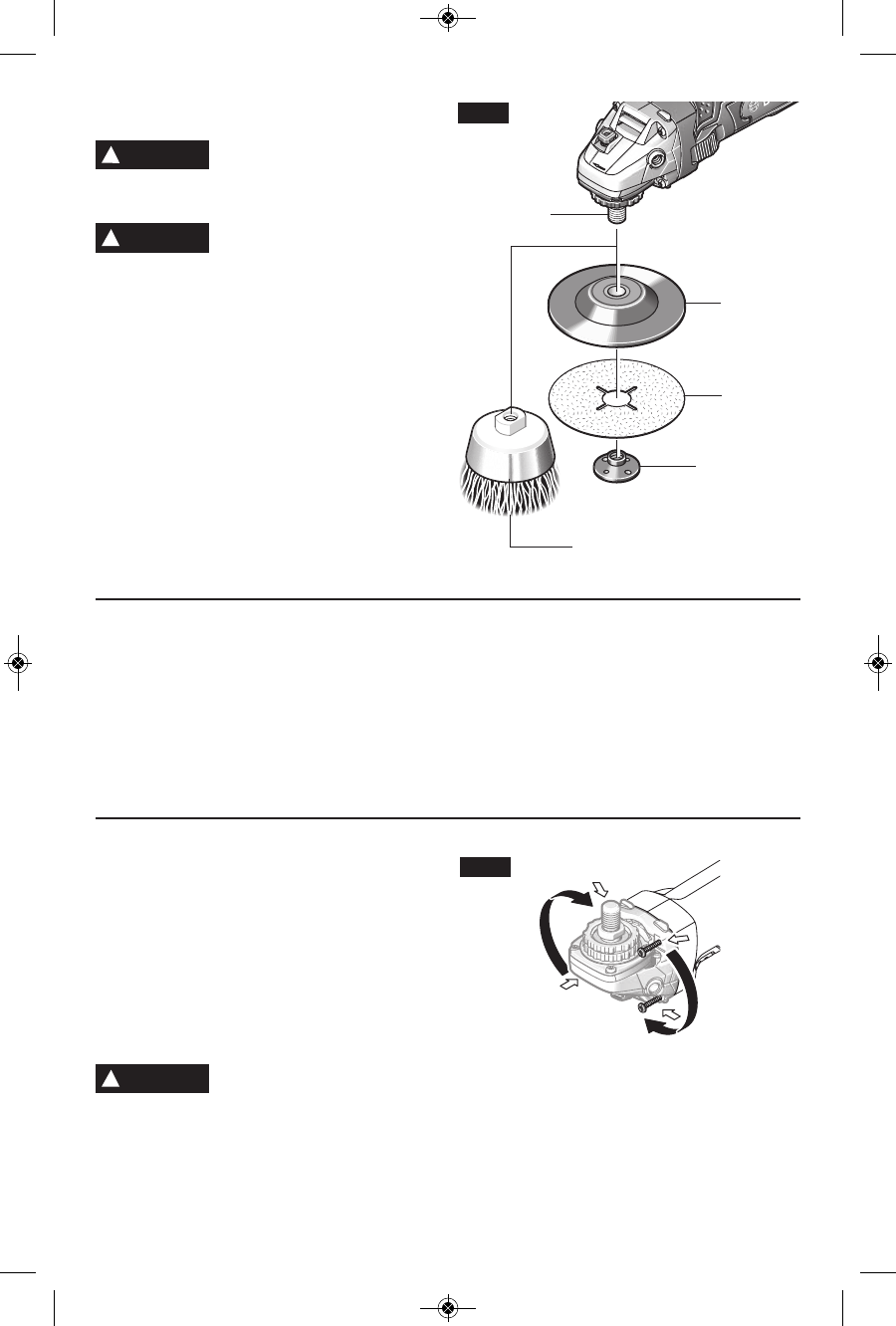
Attach hand guard (Fig. 1). Set the tool on its
top side (spindle up). Place the rubber
backing pad onto the spindle shaft. Center
the sanding disc on top of the backing pad.
Insert the lock nut through the disc and
thread onto the spindle as far as you can with
your fingers. Press in the spindle lock, then
tighten the backing pad securely with lock nut
wrench (Fig. 5).
TO REMOVE: Reverse procedure.
!
WARNING
!
WARNING
SANDING
DISC
BACKING
PAD
LOCK NUT
WIRE
BRUSH
SPINDLE
FIG. 5
!
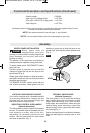
Before assembling wire brush to this tool,
disconnect from the power source. Attach
hand guard (Fig. 1). Wire brushes are
equipped with their own threaded hub, simply
thread on to spindle. Be sure to seat against
shoulder before turning tool “ON”.
TO REMOVE: Reverse procedure.
!
Before assembling wire wheel to this tool,
disconnect from the power source. Attach type
27 guard (Fig. 2). Wire wheeels are equipped
with their own threaded hub, simply thread on
to spindle. Be sure to seat against shoulder
before turning tool “ON”.
TO REMOVE: Reverse procedure.
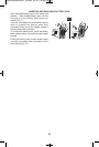
! !
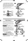
Disconnect battery pack from tool. Completely
unscrew the four screws and rotate the tool
head carefully to the new position without
removing it from the housing. For paddle
switch tools, switch should face “down”
towards work surface. For slide switch tools,
slide should face “up” towards user, so the
tool can be used for long masonry cutting
applications. Screw in and tighten the four
screws again. (Fig. 6)
Return tool head to original
position when returning to
grinding, sanding, brushing or metal cutting
applications.
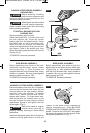
Install dust extraction guard with foot plate for
masonry cutting applications so that the
rotation of the wheel will be towards the
vacuum extraction port. Place BACKING
FLANGE and DRY DIAMOND WHEEL on the
spindle. Thread on the LOCK NUT and tighten
nut using the supplied lock nut wrench, while
holding the spindle lock in. (Fig. 7)
!
WARNING
FIG. 6
BM 2610034439 04-14_CAG180 4/1/14 7:26 AM Page 12