


8
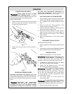
an inclination of 10° or less in a well ventilated
2. Ensure that all covers and labels are in place,
use compressor until all the above items have
3. Ensure that drain valve is closed in the vertical
position (A).
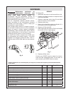
designed to protect against high pressure air
setting) is exceeded.
If the safety release valve vents
under normal operating condi-
tions stop using the compressor immediately
and send you compressor for service. If the
5. Attach hoses to the compressor (C). See
6. Flip the toggle on top of the pilot valve (D) to
the upright position. The air compressor will
unload and allow for easier engine start-up.
7. Start the engine (refer to the Engine Manual
the toggle back to the horizontal position.
stop the air compressor and refer to
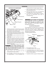
HOT SURFACES
Use care when touching exposed
metal surfaces of compressor.
engine/motor, and tubing will remain hot even
after the air compressor has been shut down.
Allow compressor to cool before moving or
attempting maintenance.
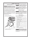
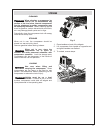
This compressor is provided with an internal reg-
ulator that controls the output pressure of two
female quick connect couplers. Regulated pres-
sure will be equal to or less than tank pressure
depending on user setting.
2. To increase pressure, turn clockwise.
3. To decrease pressure, turn counter clockwise.
4. When desired pressure is set, push regulator
knob in to lock pressure.
WARNING
WARNING
OPERATION
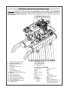
Drain Valve (A)
Pilot Valve (D)
Safety Valve (B)
Outlet Fittings (C)
Regulator
Fig. 2
TE
M
P
NORGREN
R72G
-3A
K-RM
N
INLET
OUTLET
300 PSIG
21
B
AR
150 PSIG
103 BA
R
150°F
65°C
MAX
MAX
MAX
5
1
5
0
1
0
20
0
2
5
0
30
0
0
Regulator (A)
Regulator Pressure
Gauge (B)
Fig. 3