


English - 3
Battery Charging
A battery that is new or has not been used for a
longer period does not develop its full capacity
until after approximately 5 charging/discharging
cycles.
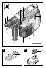
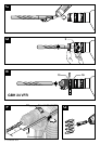
To remove the battery 10, push back the release
button 13 and pull the battery out downwards. Do
not exert any force (see figure ).
Please refer to the enclosed “Battery Charger” in-
structions for the operation of the battery charger
as well as for a description of the charging proc-
ess.
The battery is equipped with an NTC temperature
control which allows charging only within a tem-
perature range of between 0 °C and 45 °C.
A long battery service life is achieved in this man-
ner.
A significantly reduced working period after
charging indicates that the batteries are used and
must be replaced.
■ Observe the notes on environmental protec-
tion.
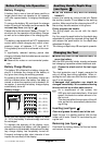
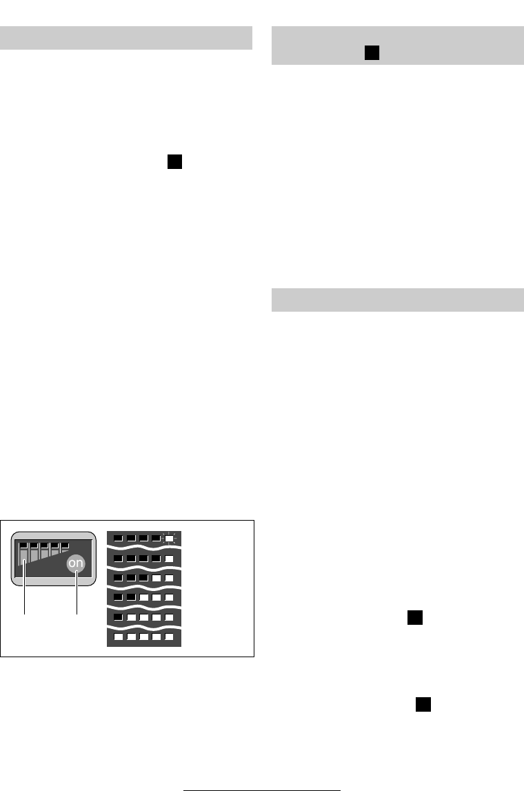
Battery Charge Display
The battery 10 is fitted with a battery charge dis-
play 9. It indicates the charge of the battery at
any given time during the working process.
By pressing the button 8, the battery charge can
also be checked when the battery has been re-
moved, or when the machine is at a standstill. Af-
ter approx. 4 seconds the battery charge display
automatically turns off.
Battery charge:
When the first display element begins to flash
(0 –10%) the battery is almost empty and must
be recharged.
To maintain the accuracy of the display, occa-
sionally discharge the battery until the speed of
the machine is considerably reduced and the bat-
tery charge display has completely turned off.
Frequent recharging after short intervals of use
impairs the accuracy of the display.
■ Use the machine only with the auxiliary
handle 11.
Loosen the handle by turning to the left. Rotate
the auxiliary handle 11 and adapt to the working
position. Make sure that the clamping band 17 of
the auxiliary handle remains in the groove.
Firmly retighten the handle.
The drilling depth can be set with the depth
stop 12.
For this, press the push-button for the depth-stop
adjustment 4, adjust the required drilling depth X
and release the push-button for the depth-stop
adjustment 4 again.
The ribbing on depth stop 12 must point upwards.
■ Before any work on the machine itself, re-
move the battery.
With the SDS-plus tool holder, simpler and easier
tool changing is possible without additional aids.
☞
Grease the shank end of the tool regu-
larly.
The dust protection cap 1 largely prevents the
entry of drilling dust during operation. When in-
serting the tool, take care that the dust protection
cap 1 is not damaged.
A damaged dust protection cap should be
changed immediately. We recommend having
this carried out by an after-sales service.
☞
As a requirement of the system, the
SDS-plus tool must rotate freely. At no-load
speed, this leads to a certain amount of ra-
dial run-out.
This does not affect the accuracy of the drill
hole, as the bit is automatically centred dur-
ing drilling.
Inserting (see figure )
Clean and grease the shank end of the tool.
Insert the tool in a twisting manner into the tool
holder until it locks. Check if it has locked by pull-
ing the tool.
Removing (see figure )
Push back the locking sleeve 2 of the tool holder
and remove the tool.
Before Putting into Operation
A
0 – 10 %
10 – 20 %
20 – 40 %
40 – 60 %
60 – 80 %
80 – 100 %
9 8
Auxiliary Handle/Depth Stop
(see figure )
Changing the Tool
F
C
D
15 • 1 619 929 589 • TMS • 08.08.02