


-10-
significant impact, the user should check
calibration by following these steps:
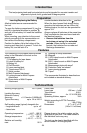
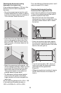
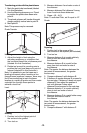
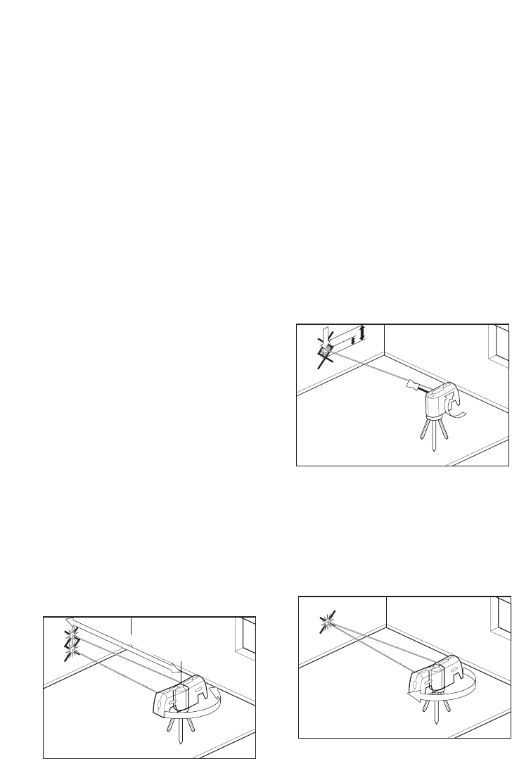
1. Select a site to be used as a calibration
range that will allow the tool to be placed
between two smooth vertical surfaces
directly opposite each other at a 100'
distance. (50' minimum)
2. Remove the two calibration plugs on the
rear and side of tool with a flathead
screwdriver. Set the plugs where they will
not be lost.
3. Set tool on a level surface at one end of
the range.
4. Set the tool in calibration mode by
pushing the power switch into the CAL
(override) position and holding for 5
seconds or more. The laser beams will
flash rapidly indicating that the unit is in
Calibration mode when the power switch
has been held in the ove rride position for
5 seconds or more. The laser beams will
continue to flash rapidly until the power
switch has been released from the CAL
(override) position. When the power
switch has been released from the CAL
(override) position the laser beams will
remain in a fast flash if the unit is level. If
the unit is out-of-level, the laser beams
will flash slowly until the device has
reached a level position. To exit
Calibration mode, push the power switch
into the CAL (over ride) position and hold
for 5 seconds. The laser beams will flash
rapidly for the 5 seconds until it exits
calibration mode. You can also exit
Calibration mode by turning the power
switch to the off position, waiting 2
seconds and back on for normal
operation. Once out of calibration mode,
the laser beams will remain steady if the
device is level or the beams will flash
slowly if the device is out-of-level.
Release the power switch from the
CAL(override) position. The unit then
operates normally.
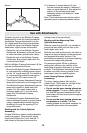
5. When in Calibration mode, position the
side laser beam (on the calibration port
side) on the vertical surface at the
opposite end of the range and mark this
point on the surface. Verify that the laser
beams are flashing fast confirming that
the device is level and in
calibration mode.
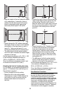
6. Rotate tool around 180 degrees, taking
care not to change the height of
the device.
7. Position the other side laser beam on the
same vertical surface and mark this point
on the surface. Verify that the laser
beams are flashing fast confirming that
the device is level and in
calibration mode.
8. If this second mark is positioned at the
same height as the mark made in step 5,
proceed to step 14, otherwise, proceed to
the next step.
9. The goal of the next few steps is to
position both side beams at a height
halfway between the marks made in step
5 and in step 7.
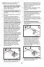
10. Insert the provided tool into the side
calibration port. Locate the calibration
screw and rotate it in a clockwise
direction to lower the beam or in the
counter clockwise direction to raise
the beam. Ensure that the beam is at a
height exactly halfway between the
marks made in Steps 5 and 7. Mark this
point on the surface.
11. Repeat Steps 6 through 10 to confirm the
calibration of the side beams and
proceed to the next step.
5
7
6
50-100 feet
10
1
1/2
11