


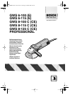

English - 4
■ Before any work on the machine itself, pull
the mains plug.
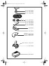
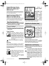
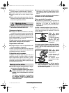
Protection Guard
■ For work with grinding or cutting discs, the pro-
tection guard 6 must be mounted.
Place the protection guard 6 on the spindle collar.
Adjust the position of the protection guard 6 to
the requirements of the work process. Clamp with
the screw 7.
The closed side of the protection guard 6
must always point to the operator.
Auxiliary Handle
■ For all work with the machine, the auxiliary
handle must be mounted.
Screw the auxiliary handle 3 on the right or left of
the machine head depending on the working
method.
Hand Guard
For work with the rubber sanding plate 13 or with
the cup brush 16/disc brush/flap disc, the hand
guard 12 (accessory) is to be mounted. The hand
guard 12 is fastened with the auxiliary handle 3.
■ Before any work on the machine itself, pull
the mains plug.
Use only grinding tools with a permissi-
ble speed at least as high as the no-load
speed of the machine.
Grinding and cutting discs become very
hot while working; do not touch until
they have cooled.
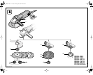
■ Clean the grinder spindle and all parts to be
mounted. For clamping and loosening the
grinding tools, lock the grinder spindle 5 with
the spindle lock button 4.
Actuate the spindle lock button 4 only when
the grinder spindle is at a standstill!
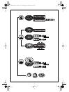
Grinding-/Cutting Disc
■ Observe the dimensions of the grinding discs.
The hole diameter must fit mounting
flange 8 (M 14), 17 (M 10). Do not use any re-
ducers or adapters.
For mounting, see the illustration page.
Screw on the clamping nut 10 and tighten with
the two-pin spanner (see Section “Quick Clamp-
ing Nut”).
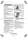
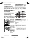
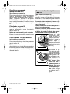
Mounting flange for
grinding spindle
M 14
An O-ring (plastic
part) is inserted in
the mounting
flange 8 around the
spigot.
If the O-ring is missing or is damaged, it must
in all cases be replaced (Order No.
1 600 210 039) before the mounting flange 8 is
mounted.
Mounting flange for
grinding spindle
M 10
The supporting
flange 17 can be
used on both sides.
Do not use any re-
ducers or adapters.
☞
After mounting the grinding tool and be-
fore switching on, check that the grind-
ing tool is correctly mounted and that it
can turn freely.
Flap Disc
(for M 14 grinder spindle)
Depending on the application, remove the protec-
tion guard 6 and mount the hand guard 12. Place
the special mounting flange 8 (accessory, Order
No. 2 605 703 028) and the flap disc on the
grinder spindle 5. Screw on the clamping nut 10
and tighten with the two-pin spanner.
Rubber Sanding Plate 13
Depending on the application, remove the protec-
tion guard 6 and mount the hand guard 12.
For mounting, see the illustration page.
Screw on the round nut 15 and tighten with the
two-pin spanner.
Mounting the
Protective Devices
Mounting the Grinding Tools
8
17
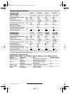
2 609 140 081 - GB Seite 4 Dienstag, 20. Januar 2004 11:34 11
16 • 2 609 140 081 • TMS • 15.01.04