


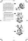

Installation of Bit
1. Insert bit to the desired depth as per the
instructions on page 7.
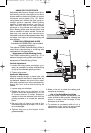
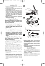
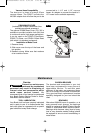
2. Press large red spindle lock button on top
of offset spindle (Fig. 26).
3.Tighten collet nut using the same collet
wrench as is used on the motor’s own
collet nut. (The collet used on the PR004
is the same type of self-releasing collet
used on the motor itself when used with
the other bases.)
4.Make a trial cut to check the depth and
readjust as necessary.
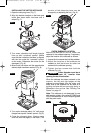
Using the Offset Router
The principles of using the offset router are
basically the same as for the regular router
set-up (motor in fixed-base assembly), with
the following differences
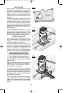
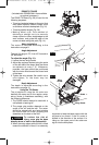
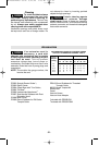
1.The offset router should be gripped with
one hand gripping the motor gripping area
and the other gripping resting on the top of
the offset spindle holding the front of the
motor (Fig. 22).
2.For routing backsplashes and other
elevated workpieces, some installers
mount the offset base to a wood block that
matches the height of the laminated
backsplash. This helps to maintain a
consistent angle between the bit’s cutter
and the workpiece and to provide addition
stability.
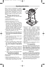
Offset Base Roller/Bushing Guide
The PR004’s roller/bushing guide is required
when edge-forming or trimming with
unpiloted non-bearing bits.
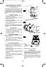
Attachment of Roller/Bushing Guide
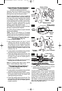
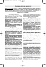
The PR004’s roller/bushing guide is attached
using two screws with a Philips screwdriver
(not included). Fig. 27
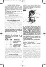
Adjustment of Roller/Bushing Guide
Whether making straight or bevel cuts, the
width of material removed is determined by
the distance between the front of the router
bit’s cutter and the front of the roller/bushing.
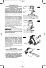
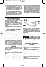
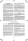
Adjust the front of the roller/bushing as
follows (Fig. 28):
1.Using a Phillips screwdriver, to adjust,
loosen screw.
2. Rotate the knurled knob on back of the
guide to move the roller/bushing in or out
to create amount of cutter exposure
needed to trim the laminate flush with the
guiding surface or to create the desired
bevel.
3.Be sure the bit clears the top of the
roller/bushing guide by at least 1/8" (3 mm)
to avoid damage.
4. Tighten clamping screw using a Phillips
screwdriver.
5. Make a trial cut to check the setting and
readjust as necessary.
Use of the PR004 with
Roller/Bushing Guide
1. With the guide installed and adjusted, the
router should be fed normally, keeping the
guide in contact with the edge of the
workpiece at all times.
2.To maintain a consistent width of cut, a
consistent angle must be maintained
between the router and the workpiece.
-16-
FIG. 26
FIG. 27
FIG. 28
Mounting
Screw
Mounting
Screw
Clamping
Screw
Knurled
Knob
BM 2609140437 05-06 5/23/06 3:15 PM Page 16