


VARIABLE SPEED CONTROLLED
T
RIGGER SWITCH
Y
our tool is equipped with a variable speed
t
rigger switch. The tool speed can be
controlled from the minimum to the maximum
nameplate RPM by the pressure you apply to
the trigger. Apply more pressure to increase
the speed and release pressure to decrease
speed. This accurate speed control enables
you to drill without center punching. It also
permits you to use as a power screwdriver.
Bits are available for driving screws as well as
running bolts and nuts.
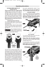
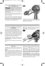
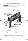
REVERSING SWITCH BUTTON
The reversing switch button is located above
the trigger switch and is used to reverse
rotation of the bit.
For forward rotation, (with the chuck pointed
away from you) move button to the far left. For
reverse rotation move the button to the far
right. (Fig. 2)
Do not change direction of
rotation until the tool comes to
a complete stop. Shifting during rotation of the
chuck can cause damage to the tool.
SLIP CLUTCH
The tool has an internal preset clutch. The
clutch is set such that sufficient force is
transmitted to the bit for most drilling conditions
but it will slip when bit binds in the hole or the
tool is overloaded. Be aware that due to
required clutch setting, you may experience a
torque reaction an instant before the clutch
slips. This torque reaction will twist the body of
the rotary hammer in the opposite direction as
the bit rotates, i.e., counterclockwise. As clutch
is slipping, the bit will most likely stop rotating.
When the binding force on the bit is removed
the clutch automatically resets. If you
e
xperience bit binding and clutch begins to
s
lip, immediately turn the tool "OFF" and
c
orrect the condition leading to the bit binding.
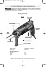
AUXILIARY HANDLE
The auxiliary handle will provide additional
control, support and guidance for the tool. The
handle is adjustable around the 360° handle
collar mount. To mount, loosen wing knob and
slide handle completely over chuck onto the
collar mount and tighten wing knob (Fig. 3).
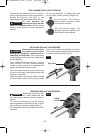
DEPTH GAUGE
Your drilling depth can be pre-set and/or
repeated by using the depth gauge.
Setting depth: After the auxiliary handle is
installed, make sure the accessory has been
fully inserted into the tool holder before setting
the depth gauge (Fig. 4).
To adjust depth, push down on the depth
gauge release lever, slide the depth gauge to
desired depth and release pressure on lever to
lock the depth gauge in place (Fig. 4).
-7-
Operating Instructions
!
CAUTION
FIG. 2
REVERSING
SWITCH
BUTTON
WING
KNOB
FIG. 3
DEPTH
GAUGE
RELEASE
LEVER
DEPTH
GAUGE
FIG. 4
AUXILIARY
HANDLE
BM 1619P00836 12-06 1/5/07 9:43 AM Page 7