


12
MiniCAFS 2.1A Operating Manual
GP/211/05 Issue 2. April 2005
©Hale Products Europe. Our policy is one of continuous development. We therefore
reserve the right to amend specifications without notice or obligation.
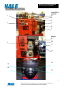
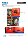
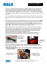
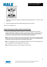
1. If the unit is installed in the side locker of a fire fighting vehicle, provision must be made
for access to the engine oil dipstick (A), compressor oil-fill (B) and sight glass (D), all
located on the rear side of the MiniCAFS. The drive motor is air-cooled, and cooling air
must be allowed to flow unhindered into and out of the unit. Avoid any enclosing cladding
at a distance of approx. 300mm around the engine cooling air intake. Compressor oil filter
is item (C).
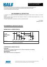
2. The cooling line (L) from the heat exchanger should return to the top of the vehicle water
tank using φ 13 min. diameter flexible hose. There must be no kinks or obstructions in this
line.
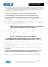
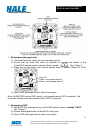
3. The preferred method of supplying foam agent is from an on board foam tank. This MUST
be mounted to give a head of foam agent to the FoamLogix pump. The Low-level switch
(Supplied) must be installed so that the circuit becomes closed when the foam tank is
empty. Connect the low-level switch connection on the foam tank to the Interlock wiring
harness (M) on the MiniCAFS, using the extension harness provided.
Note: the low foam level switch must be installed in the tank in the correct orientation.
The switch device has a raised marker on the casing where the wires enter the device.
This marker must be installed at the 12 o clock (top) position for correct functioning.
The foam tank requires a 23mm hole for secure fitting of the switch device and the
maximum allowable thickness of tank wall material is 4mm.
The switch device should be installed at a location in the tank wall that allows for
activation when there are approximately 3 litres of foam left before running out.
This marker must be
at 12 o clock (top)
when the switch
device is installed
Connection (M)
for low foam level
switch
(L) Compressor
cooling return
line, inside
panel
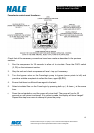
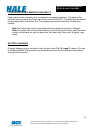
4. Connect the foam agent supply to the inlet connection on the FoamLogix pump (F),
situated on top of the unit. Note the location of the By-pass valve and connection point
(G) and the foam filter (E).
Note. Connections must be secure and pressure tight if the FoamLogix pump is
to operate correctly.
Water supply of
between 4-10 bar
connected to here.
CAFS or foam
discharges here