


9
MiniCAFS 2.1A Operating Manual
GP/211/05 Issue 2. April 2005
©Hale Products Europe. Our policy is one of continuous development. We therefore
reserve the right to amend specifications without notice or obligation.
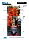
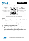
INTRODUCTION
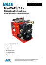
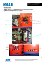
The MiniCAFS is a Compressed Air Foam System comprising of three major components –
air compressor (driven by air-cooled engine), FoamLogix (foam proportioning unit) and
manifold (foam mixing and control system). All the components are in one integrated module
designed to fit in the standard envelope of a DIN 8kVA generator.
Water is supplied from the main pump at a pressures between of 4-10 bar, depending on
requirements or operator preference, and fed, via non-return valves, into a manifold
assembly where flowrate is measured and a metered amount of foam is injected. This
foam/water solution is then fed through an air control valve (ARC) at which wet or dry foam is
selected (air ratio control section of manifold). Compressed air is then injected and the
resulting foam/water/air solution is thoroughly mixed (X-mixers) before being fed to a
discharge connection.
The unit is provided with several safety interlocks to ensure that: -
1. Foam cannot be injected unless water is flowing through the unit.
2. Air cannot be injected unless foam and water are flowing through the unit. This
prevents “slugging” in the discharge line caused by air and water, which cannot mix
3. A low level switch in the foam tank will stop air injection when the tank is empty to
prevent slugging.
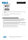
Compressor
The rotary twin-screw compressor provides 50 scfm of compressed air at 7 bar and is driven
by an 18hp air-cooled petrol engine, running generally at a constant speed. The engine has
its own built in 8.5 litre fuel tank, which is sufficient for in excess of one hours running. The
oil in the rotary air compressor is cooled by water taken from the vehicle main pump via the
water supply line. To ensure adequate cooling water must be supplied to the unit prior to
starting the engine. A return line delivers the cooling water back to the vehicle tank.
Alternatively, the water can be run to drain, but this is not recommended.
If the unit is run from a closed tank the water will gradually heat up and at an increasing rate
as the volume of water reduces.
NOTE: The compressor should never be run without the pump providing a water supply for
cooling.
The compressor will reject approx. 8.0 kW of heat energy to cooling, and the installer must
consider this additional thermal load
A blowdown valve is fitted to the compressor to remove any constrained pressure in the
system when the compressor is stopped.