


5
To replace the belt:
1. Use a belt with same section type or similar size. Do
not substitute a “ FHP” type belt. When installing the
new belt, do not use a tool (screwdriver or pry--bar) to
force the belt over the pulley flanges, this will stress
the belt and cause a reduction in belt life.
2. Loosen the motor mounting plate front bolts and rear
bolts.
3. Push the motor and its mounting plate towards the
blower housing as close as possible t o reduce the cen-
ter distance between fan shaft and motor shaft.
4. Remove the belt by gently lifting the old belt over
one of the pulleys.
5. Install t he new belt by gently sliding the belt over
both pulleys and then sliding the motor and plate
away from the fan housing until proper tension is
achi eved.
6. Check the alignment of the pulleys, adjust if neces-
sary.
7. Tighten all bolts.
8. Check the tension after a few hours of runtime and
re--adjust as required.
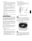
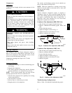
Adjustable-- Pitch Pulley on
Motor
The motor pulley is an adjustable--pitch type that allows a
servicer to implement changes in the fan wheel speed to
match a s--installed ductwork systems. The pulley consists
of a fixed flange side that faces the motor (secured to the
motor shaft) and a movable flange side that can be rotate d
around the fixed flange side that increases or reduces the
pitch diameter of this driver pulley. (See Fig. 6.)
As the pitch diameter is changed by adjusting the position
of the movable flange, the centerline on this pulley shifts
laterally (along the motor shaft). This creates a
requirement for a realignment of the pulleys after any
adjustment of the movable flange. Also reset the belt
tension after each realignment.
Check the condition of the motor pulley for signs of wear.
Glazing of the belt contact surfaces and erosion on these
surfaces are signs of improper belt tension and/or belt
slippage. Pulley replacement may be necessary.
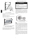
To change fan speed:
1. Shut off unit power supply.
2. Loosen belt by loosening fan motor mounting nuts.
(See Fig. 5.)
3. Loosen movable pulley flange setscrew. (See Fig. 6.)
4. Screw movable flange toward fixed flange to increase
speed and away from fixed flange to decrease speed.
Increasing fan speed increases load on motor. Do not
exceed maximum speed specified.
5. Set movable flange at nearest keyway of pulley hub
and tighten setscrew to torque specifications.
To align fan and motor pulleys:
1. Loosen fan pulley setscrews.
2. Slide fan pulley along fan shaft. Make angular align-
ment by loosening motor from mounting.
3. Tighten fan pulley setscrews and mot or mounting
bolts to torque specifications.
4. Recheck belt tension.
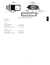
C07075
Fig. 6 -- Supply--Fan Pulley Adjustment
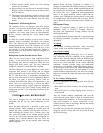
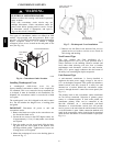
Beari ngs
This fan system uses bearings featuring concentric split
locking collars. The collars are tightened through a cap
screw bridging the split portion of the collar. The cap
screw has a Torx T25 socket head. To tighten the locking
collar: Hold the locking collar tightly against the inner
race of the bearing and torque the cap screw to 65 -- 70
in-lb (7.4--7.9 Nm). (See Fig. 7.)
C08121
Fig. 7 -- Tightening Locking Collar
Motor
When replacing the motor, also replace the external--tooth
lock washer (star washer) under the motor mounting base;
this is part of the mot or grounding system. Ensure the
teeth on the lock washer are in contact with the motor ’s
painted base. Tighten motor mounting bolts to 120 +/ -- 12
in-- lbs. (13.5 +/-- 1.3 Nm).
580J