


14
www.chpower.com
Pre-Operation (Continued)
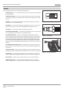
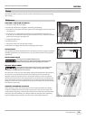
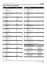
ELECTRONICS ON / OFF SWITCH
Located under the top of the rubber grip is an ON/ OFF switch for the tool’s electronic
function, low nail indicator LEDs (See Figure 21).
To utilize the function, grip the tool by the handle, depressing the switch. Hold the
switch firmly for continuous, uninterrupted function. Power is maintained for 5-10
seconds after releasing the switch. This extra time is helpful when adjusting your grip
on the tool which may temporarily undepress the switch.
Operation
FIRING THE NAILER
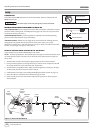
1. Load fasteners (see Loading / Unloading the Nailer section).
2. Connect the air supply to the nailer.
An improperly functioning tool must not be used. Do not actuate
the tool unless the tool is placed firmly against the work piece.
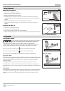
In Sequential Mode
Press the conversion switch to the “
” side to activate Sequential Mode.
1. Slightly depress Work Contact element (WCE) against work surface.
2. Fully depress WCE.
3. Pull trigger. Fastener will be driven into workpiece.
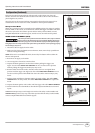
In Bump Mode
Press the conversion switch to the “
” side to activate Bump Mode.
1. Remove tool from work surface. DO NOT point tool at yourself or others.
2. Pull trigger.
3. Firmly depress Work Contact element (WCE) against work surface. Tool will cycle.
4. Remove tool from work surface. Move tool to the next area where fastener is to be
driven and repeat.
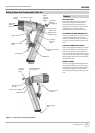
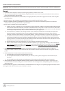
LOW NAIL INDICATOR LIGHTS
The tool is equipped with lights on either side of the tool near the nose. Turn the
electronics switch to the ON position. When the nail count becomes 7 or so nails
remaining in the magazine, the lights will come on yellow. You may reload at that time
(See Loading the Nailer section). When the nail count becomes 3 or so remaining nails,
the Anti-Dry Fire will engage and the lights will turn red. You MUST reload at that time.
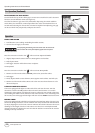
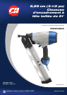
BUBBLE LEVEL
The tool is equipped with a bubble level located on the head cap. When the gun is in a
horizontal driving orientation, a level condition can easily be observed and controlled
by simply aligning the tool in such a manner whereas the bubble is between the center
markings on the length of the level. The same is true when in a vertically downward
driving orientation by aligning the tool such that the bubble is centered in the circular
marking at the top of the level.
Figure 23 - Bubble Level
CHN70900
Figure 22 - Low Nail Indicator Lights
Operating Instructions and Parts Manual
Figure 21 - Electronic ON/OFF Switch