


and the proper use of the
equipment. Follow all instructions.
• Only persons well acquainted with
these rules of safe operation should
be allowed to use the unit.
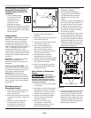
Components
Pressure switch - Auto/Off Switch - In
the "
AUTO" position, the compressor
shuts off automatically when tank
pressure reaches the maximum preset
pressure. In the "
OFF" position, the
compressor will not operate. This switch
should be in the "
OFF" position when
connecting or disconnecting the power
cord from the electrical outlet or when
changing air tools.
Regulator - The regulator controls the
amount of air pressure released at the
hose outlet.
ASME Safety Valve - This valve
automatically releases air if the tank
pressure exceeds the preset maximum.
Pressure Gauges - The gauge attached
to pressure switch will show air
pressure in tank. The gauge attached to
regulator will show air pressure at the
hose outlet.
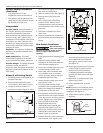
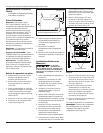
Removal of Existing Switch
1. Disconnect power and release all air
pressure from tank.
2. Remove existing pressure switch
cover screw(s), then remove cover.
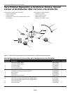
3. Locate cut-outs on the back of
pressure switch (See Figure 3). Insert
tip of small screwdriver into cutouts,
then push to release wires.
4. Remove ground screw (See Figure 3).
5. Remove strain relief screw (See
Figure 3).
6. Pull unloader tube off existing
pressure switch. Remove screw
holding pressure switch to pressure
switch assembly. Then remove switch
from unit.
7. Disconnect unloader tube from
check valve.
8. Remove the remainder of pressure
switch assembly by unscrewing tank
fitting.
New Switch Installation
New switch must
have same maximum
pressure as existing switch. Pressure
rating is listed on the bottom of
assembly.
1. Screw pressure switch assembly onto
tank.
2. Replace existing unloader tube
connection at check valve with new
quick connect supplied in kit.
3. Insert new unloader tube into quick
connect fitting on check valve.
4. Insert other end of unloader tube
into unloader valve on pressure
switch. Unloader tube can be cut if
supplied length is too long.
5. Loosen pressure switch cover screw,
then remove cover.
6. Two strain relief clamps will be
provided in the kit. Determine which
strain relief clamp to use based on
the diameter of the line cord.
7. Loosely attach strain relief clamp to
pressure switch with screw provided
in kit. Insert motor and line cord into
switch. Tighten strain relief clamp
screw to hold cords securely.
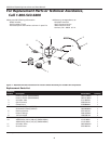
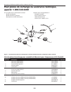
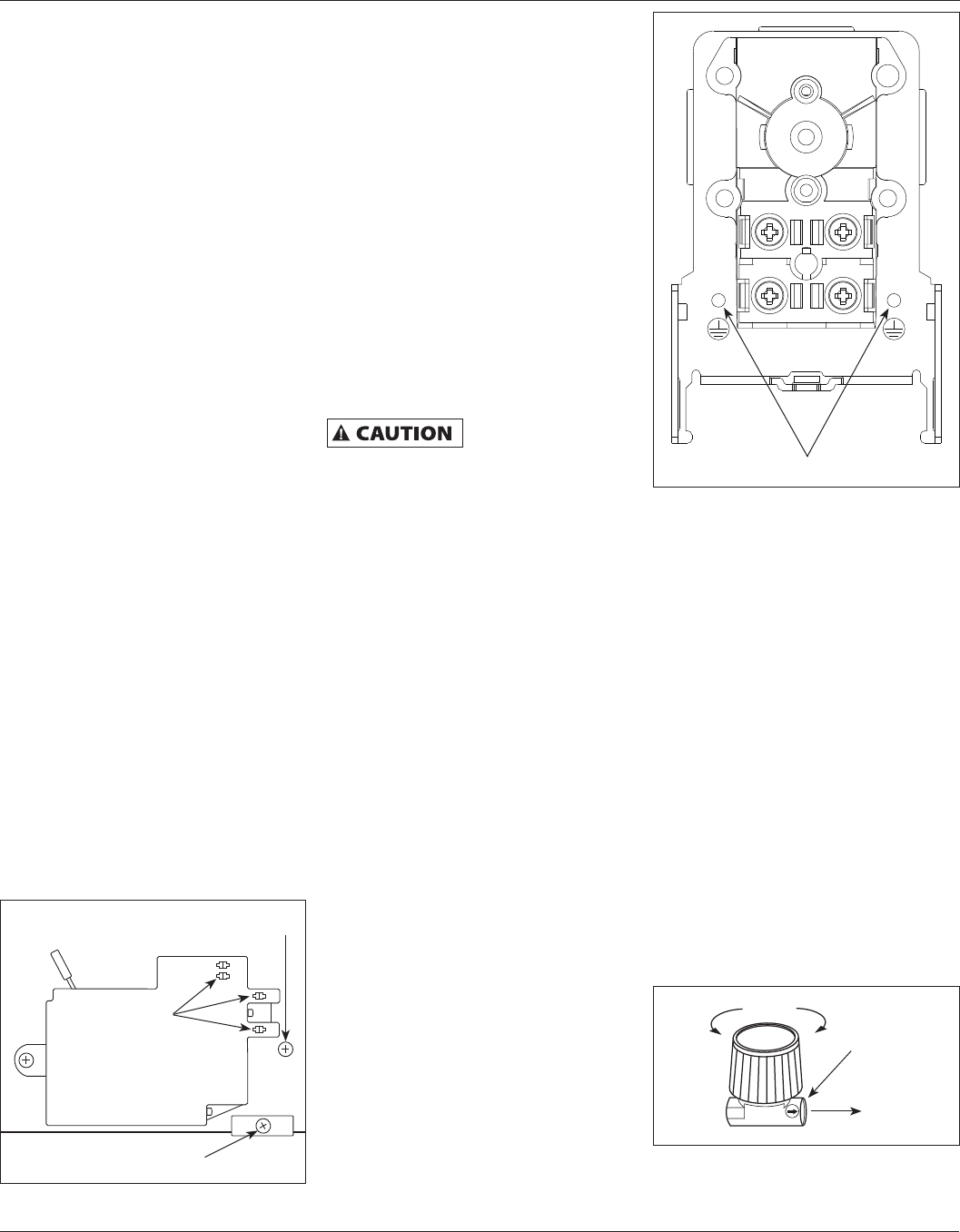
8. Position black motor wire
underneath screw head #4 (See
Figure 4), then tighten screw to
secure wire. Position black line wire
underneath screw head #2, then
tighten screw to secure wire.
9. Position white line wire underneath
screw head #1, then tighten screw
2
Additional Operating Instructions and Parts Manual
www.chpower.com
General Safety Information
(Continued)
to secure wire. Position white motor
wire underneath screw head #3,
then tighten screw to secure wire
(See Figure 4).
10. Attach green ground wire from line
cord to inside of pressure switch
with ground screw provided in
kit. Repeat procedure with green
ground wire from motor cord. (See
Figure 4).
11. Place cover on pressure switch and
tighten cover screw.
12. Screw regulator onto pressure
switch.
NOTE: Ensure air flow indicator arrow
on regulator body points away from
compressor (See Figure 5).
13. Attach outlet pressure gauge to
regulator.
MTR
LINE
MTR
LINE
1
2
3
4
Figure 4
Ground terminals
Figure 5
Hose
Outlet
Air Flow
Figure 3
Cutouts
Strain Relief Screw
Ground Screw