


25 Pg
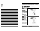
Operating Instructions and Parts Manual
4
www.chpower.com
Charging Battery
(Cont’d.)
battery pack is connected to the
charger and the charger is plugged in.
With normal use, the battery pack will
be fully charged after about three (3)
to six (6) hours with charger
DG111800CH and one (1) to two (2)
hours with fast charger DG151800CH.
The fast charge battery DG151800BP
will charge in either charger. The
battery DG111800BP will charge only
in charger DG111800CH. Disconnect
charger from power source when not
in use.
IMPORTANT: THE BATTERY PACK
SHOULD NOT BE LEFT ON THE
CHARGER FOR MORE THAN FORTY-
EIGHT (48) HOURS.
Operation
VARIABLE-SPEED TRIGGER
SWITCH (some models)
If your Drill/Driver is equipped with a
variable-speed trigger switch, the
pressure you apply to the trigger
controls the tool speed. Apply more
pressure to increase the speed and
release pressure to decrease speed.
This accurate speed control allows you
to drill without center-punching and
to use the Drill/Driver as a power
screwdriver. Bits are available for
driving screws as well as running bolts
and nuts.
FORWARD/REVERSE BUTTON
This Drill/Driver is equipped with a
forward/reverse lever which is used to
change the rotation of the chuck. Do
not attempt to change the rotation
unless the chuck is completely stopped.
Moving the
Forward/Reverse
Button while chuck is rotating can
damage the tool.
For forward rotation, firmly press in on
the lever marked FWD. For reverse
rotation, firmly press in on the lever
marked REV.
TRIGGER LOCK
To activate trigger lock, move the
forward/reverse lever so it is centered
in the handle.
GEAR SHIFTING (DG151800CK only)
The DG151800CK Drill/Driver is
equipped with two separate gear
ranges, low and high. Low gear
provides high-torque and slower
drilling speeds for heavy duty work or
for driving screws. High gear provides
faster speeds for drilling lighter work.
NOTICE
To change speeds, slide switch to the
high or low position. Actuate trigger
slightly if the gear shift does not fully
engage.
Note: If Drill/Driver is running, but the
chuck will not turn, check to make sure
the gear shifting switch is pushed fully
into desired setting.
ADJUSTABLE CLUTCH
This Drill/Driver features 16 clutch
settings. Output torque will increase as
the clutch ring is rotated from 1 to 16.
1 to 2for driving small screws.
3 to 4for driving screws into soft
materials or plastics.
5 to 7for driving screws into
softwoods.
8 to 10for medium woods.
11 to 14for driving screws into
medium / hard woods.
15 to 16for driving screws into metal.
The “drill” position locks up the clutch
to permit heavy-duty drilling and
driving work. It also allows bits to be
changed quickly and easily in the
keyless chuck.
INSERTING BITS
Move Forward/Reverse Button to the
center “Off” position. Remove battery
pack (See “Charging Battery” section)
and rotate the clutch ring to the drill
bit symbol. Rotate the chuck sleeve
counterclockwise (viewing from chuck
end), and open chuck to approximate
drill bit diameter. Insert a clean bit up
to the drill bit flutes for small bits, or
as far as it will go for large bits. Close
chuck by rotating the chuck sleeve
clockwise and securely tighten by
hand.
Do not use the
power of the drill
to loosen or tighten bit while holding
chuck. The spinning chuck will cause
friction burn or hand injury.
REMOVING CHUCK
Remove battery pack. Rotate clutch
ring to drill bit symbol and open chuck
all the way. Turn left-hand-threaded
screw inside chuck clockwise, and
remove it . Insert the short arm of a
3/8" hex key wrench and close jaws on
flats of wrench.
Strike long arm of wrench sharply
counterclockwise, remove wrench and
unthread chuck from spindle.
INSTALLING CHUCK
To install chuck, reverse “Removing
Chuck” procedure. Always keep the
!
CAUTION
spindle threads, chuck threads, and
securing screw free of debris.
GENERAL DRILLING
The front end of
the Drill/Driver may
be made “live” if the tool drills into
live wiring in the wall. TO PREVENT
ACCIDENTAL ELECTRICAL SHOCK, HOLD
DRILL/DRIVER ONLY BY THE SOFT GRIP
HANDLE.
Safety glasses must be worn during
operation.
1. Set torque adjusting collar for
drilling operation and set speed
selector to appropriate speed.
2. Be sure drill bit is securely gripped in
chuck.
3. Set FORWARD/REVERSE BUTTON for
clockwise rotation.
Make sure work is
held securely in a
vice or clamped in place prior to
starting drilling operation. Loose work
may spin and cause bodily injury.
4. Locate exact center for hole to be
drilled and using a center punch,
make a small dent in work.
5. Place tip of drill bit in dent made by
center punch, hold drill square with
work, and start the motor.
Applying too
much pressure may
cause the bit to overheat or break,
resulting in bodily injury or damaged
drill bits.
Apply steady, even pressure to keep
drill bit cutting. Too little pressure
will keep the bit from cutting.
Eventually, the excessive friction
created by sliding over the surface
will dull the cutting edges.
Always be alert
and brace yourself
against the twisting action of the drill.
6. If drill stalls or becomes jammed in
the hole, release trigger
immediately, remove drill bit from
work and determine cause of
stalling or jamming.
Do not squeeze
trigger on and off
in an attempt to free a stalled or
jammed drill. This will damage the
motor.
The direction of rotation may be
reversed to help free a jammed bit.
Be sure direction of rotation is
RESET before attempting to
continue drilling.
NOTICE
!
CAUTION
!
CAUTION
!
CAUTION
!
WARNING
!
WARNING
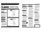
Funcionamento
(continuação)
Não use
a força da furadeiras para afrouxar ou
para ajustar uma broca enquanto
estiver segurando o mandril. Ao girar,
o mandril pode causar queimaduras por
fricção ou lesões na mão.
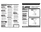
COMO RETIRAR O MANDRIL
Retire a bateria. Gire o anel de
embreagem até o símbolo da broca da
furadeira e abra completamente o
mandril. Gire o parafuso com rosca
para a esquerda dentro do mandril
girando até a direita e retire-o.
Coloque o braço curto de uma chave
hexagonal 3/8" e feche as castanhas
sobre as partes planas da chave.
Aplique um movimento giratório
brusco em sentido anti-horário sobre
o braço longo da chave, retire a chave
e desrosqueie o mandril da broca.
COMO INSTALAR O MANDRIL
Para instalar o mandril, faça de maneira
inversa o procedimento “Como retirar o
mandril”. Mantenha sempre as roscas
da broca, as roscas do mandril e o
parafuso de fixação livre de resíduos.
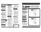
PERFURAÇÃO EM GERAL
A extremidade frontal da
Furadeira/Parafusadeira pode conduzir
corrente se a ferramenta perfurar
cabos energizados dentro da parede.
PARA EVITAR CHOQUES ELÉTRICOS
ACIDENTAIS, SEGURE A
FURADEIRA/PARAFUSADEIRA SOMENTE
PELO CABO DE EMPUNHADURA MACIA.
Devem ser usados óculos de segurança
durante a operação.
1. Ajuste o anel de torque para a
operação de perfuração e ajuste
o seletor de velocidade para a
velocidade adequada.
!
AVISO
!
AVISO
!
CUIDADO
2. Assegure-se de que a broca da
furadeira esteja fixada de maneira
segura no mandril.
3. Ajuste o BOTÃO DE
AVANÇO/RETROCESSO para rotação
em sentido horário.
Antes de
começar a perfuração, assegure-se de que
o material a ser trabalhado esteja fixado
de maneira segura em um torno de
bancada ou preso ao local. O material
solto pode girar e causar lesão corporal.
4. Localize o centro exato do orifício a
ser perfurado e, usando um punção,
faça um pequeno entalhe.
5. Crave a ponta da broca no entalhe
feito pelo punção marcador, segure
a furadeira em ângulo reto com o
trabalho e acione o motor.
A aplicação de pressão excessiva pode
causar o superaquecimento ou quebra
da broca, resultando em lesão corporal
ou danos às brocas.
Aplique pressão uniforme e
constante para que a broca
continue cortando. A pressão
excessivamente pequena impedirá
que a broca corte. Ao final, o atrito
excessivo criado pelo deslizamento
sobre a superfície irá reduzir o corte
das bordas de corte.
Esteja
sempre alerta e prepare-se contra a
ação giratória da furadeira.
6. Se a furadeira parar ou emperrar no
interior do orifício, solte
imediatamente o gatilho, retire a
broca de perfuração do trabalho e
determine a causa da parada ou
emperramento.
Não aperte e solte o gatilho na tentativa
de liberar uma furadeira parada ou
emperrada. Isso pode danificar o motor.
NOTA
!
CUIDADO
!
CUIDADO
!
CUIDADO
A direção da rotação pode ser
invertida para ajudar a liberar uma
broca emperrada. Certifique-se de
REAJUSTAR a direção da rotação
antes de reiniciar a furação.
7. Reduza a pressão na furadeira antes
que a broca corte o material, para
evitar lascas de madeira ou a parada
no metal.
8. Quando a broca tiver penetrado
completamente o material e estiver
girando livremente, retire-a da
superfície trabalhada enquanto o
motor ainda estiver ligado e a seguir
desligue a furadeira.
COMO FURAR MADEIRA
Além das instruções enumeradas na
seção PERFURAÇÃO EM GERAL, as
seguintes também se aplicam:
1. Ao usar uma broca helicoidal na
Madeira, retire-a freqüentemente
do orifício para limpara as lascas
que se acumulam nas ranhuras. Isso
ajuda a evitar que o trabalho sofra
superaquecimento ou se queime.
2. Se utilizar um bloco de apoio para
que a parte posterior do material a
ser perfurado não se estilhace,
prenda-o de forma segura no local
apropriado. Se não for usado um
bloco de apoio com brocas chatas
ou serras tipo copo, libere a pressão
assim que a ponta da broca
atravessar o material e complete o
orifício a partir do lado oposto.
COMO FURAR METAL
Além das instruções enumeradas na
seção PERFURAÇÃO EM GERAL, as
seguintes também se aplicam:
1. Para perfurar metais use somente
brocas helicoidais de aço para alta
velocidade, de boa qualidade e
afiadas.
2. Comece a perfurar com baixa
velocidade e aumente
gradualmente a velocidade à
medida que a broca vai cortando.
Quanto mais duro o material,
menor a velocidade necessária.
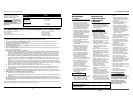
Tamanhos sugeridos de orifícios para parafusos para madeira
Diâmetro da broca Diâmetro da furadeira piloto
Tamanho para o orifício Madeira Madeira
do parafuso de passagem mole dura
#6 5/32 (.156) 1/16 (.062) 5/64 (.078)
#8 11/64 (.172) 5/64 (.078) 3/32 (.093)
#10 13/64 (.203) 3/32 (.093) 7/64 (.109)
#12 15/64 (.234) 7/64 (.109) 1/8 (.125)
DG111800CD & DG151800CD