


3
FP209800
www.chpower.com
Installation (Continued)
2. If repair or replacement of cord or
plug is necessary, do not connect
grounding wire to either flat blade
terminal. The wire with insulation
having an external surface that
is green (with or without yellow
stripes) is the grounding wire.
Never connect
green (or green and
yellow) wire to a live terminal.
3. Check with a qualified electrician or
serviceman if grounding instructions
are not completely understood, or
if in doubt as to whether product is
properly grounded. Do not modify
plug provided; if it will not fit outlet,
have proper outlet installed by a
qualified electrician.
Overheating, short
circuiting and fire
damage will result from inadequate
wiring, etc.
Operation
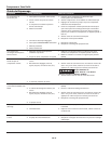
DEFINITION OF TERMS
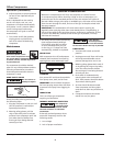
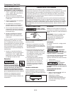
ON / OFF Switch ( I / O ) - Push
switch to the ON ( I ) position to turn
compressor on. Push switch to the
OFF ( O ) position to turn compressor
off. This switch should be in the
OFF ( O ) position when connecting
/ disconnecting power cord from
electrical outlet or when changing tools.
ON Position OFF Position
Figure 3
Pressure Switch (located internally)-
When the compressor is turned ON,
this switch will shut compressor off
automatically when tank pressure
reaches maximum shut-off / cut-out
pressure. If compressor remains on and
air is depleted from tank, this switch
will allow compressor to automatically
restart at the restart / cut-in pressure.
Regulator - The regulator controls the
amount of air pressure released at the
hose outlet. Turning the regulator knob
clockwise (to the right) will increase air
pressure at the outlet. Turning the knob
counter-clockwise (to the left) will lower
air pressure to the outlet. Turning knob
fully counter-clockwise will shut off flow
of air completely.
Pressure Gauges - There are two
gauges located next to the regulator.
These gauges read air pressure in
pounds per square inch (psi) The larger
gauge shows pressure at the outlet.
Make sure this gauge reads ZERO
(by adjusting the regulator) BEFORE
changing air tools or disconnecting
hose from outlet. The small gauge
shows pressure in the tank indicating
compressor is building pressure
properly.
ASME Safety Valve - This valve
automatically releases air if the tank
pressure exceeds the preset maximum.
Handle - Designed to move the
compressor.
Motor Reset - (not shown, located
inside motor). Designed to keep the
motor from overheating. The motor has
an auto reset protector. To reset once
the motor has cooled, turn the switch
to the OFF position, then to the ON
position.
Drain Valve - This valve is located on
the bottom of the tank. Use this valve
to drain moisture from the tank daily to
reduce the risk of corrosion.
Figure 4
LUBRICATION
This is an oilless product and DOES NOT
require lubrication to operate.
BEFORE FIRST START-UP
BREAK-IN PROCEDURE
(Complete this procedure before using
compressor for the first time. Once
completed, it is not necessary to repeat.)
1. Turn regulator knob fully clockwise
(to the right) to open air flow.
2. Do not attach a hose or any other
fitting to the compressor.
3. Turn on/off switch to OFF position.
4. Plug in power cord.
5. Turn on/off switch to ON position.
Allow compressor to run for 5
minutes.
6. Turn on/off switch to OFF position.
7. Unplug power cord.
BEFORE EACH START-UP
OPERATING PROCEDURE
1. Turn switch to OFF ( O ) position and
plug in power cord.
2. Turn regulator knob
counterclockwise to close air flow.
3. Turn switch to ON ( I ) position.
4. Compressor will build to maximum
pressure and shut off.
5. With hose attached to outlet of
compressor, attach tire chuck or
other tool to open end of hose.
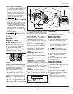
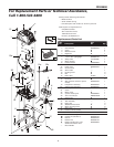
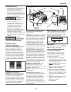
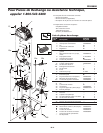
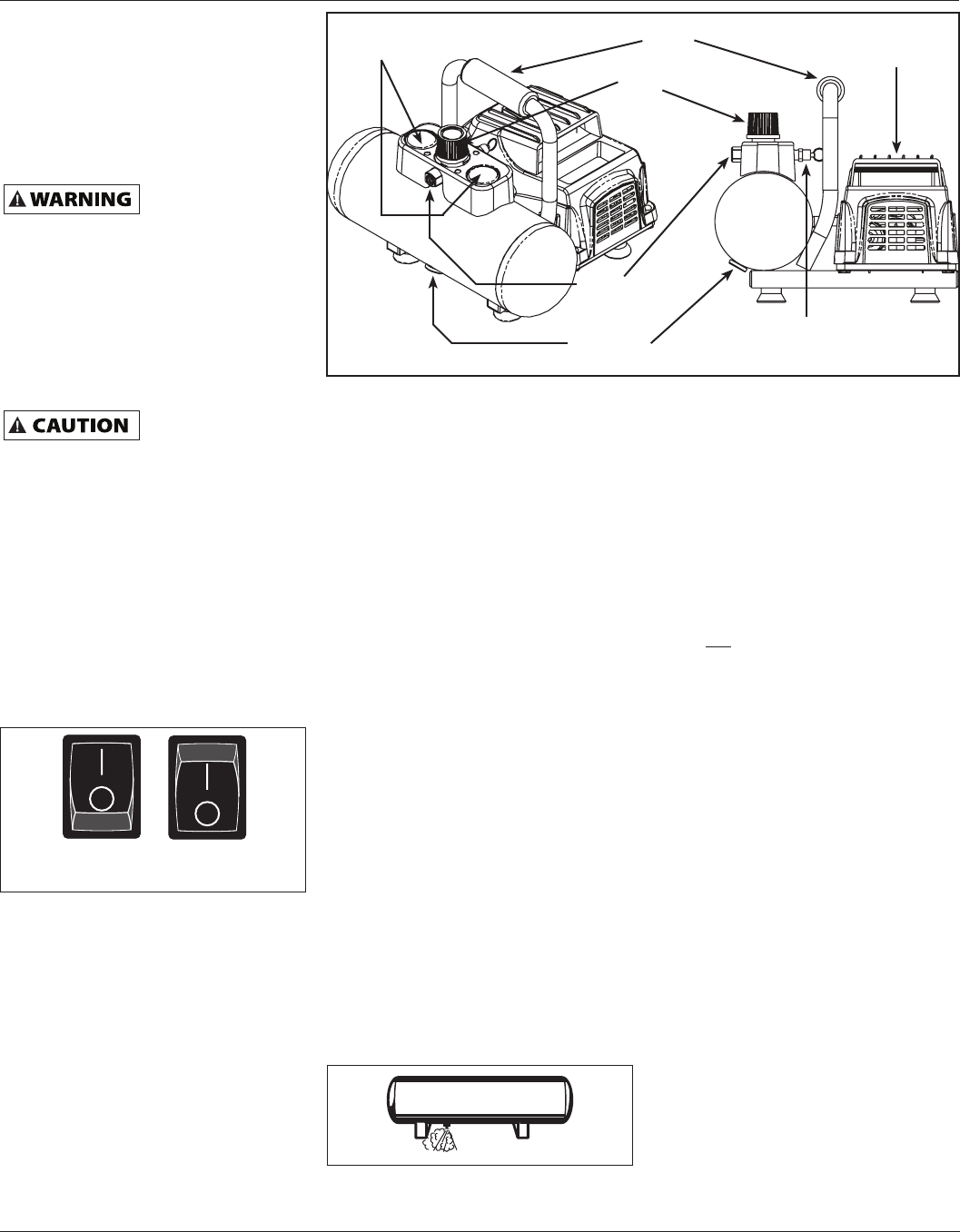
Figure 2 - Unit Identification
Pressure
Gauge
ON/OFF Switch
Safety Valve
Drain Valve
Air Outlet
Handle
Regulator
Knob