


Cómo usar la Herramienta
(Cont.)
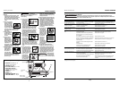
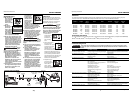
CONEXIÓN RECOMENDADA
La ilustración de abajo le muestra la
conexión recomendada para la herra-
mienta.
1.
El compresor de
aire debe tener
la capacidad de
suministrar un
mínimo de 4,14
bar cuando la
herramienta esté en uso. Si el sumin-
istro de aire es inadecuado podría
haber pérdida de potencia y falta de
consistencia en el funcionamiento.
2. Puede utilizar un lubri-
cador para lubricar la
herramienta.
Igualmente, puede
utilizar un filtro para
remover las impurezas
líquidas y sólidas que
podrían oxidar u obstruir las partes
internas de la herramienta.
3. Use
mangueras
de aire de
9,5 mm
(3/8”) dis-
eñadas
para presiones
mínimas de trabajo de 10,34 bar.
Use mangueras de aire de 12,7 mm
(1/2”) si la longitud de las mismas es
de 15 m ó más. Para un mejor
rendimiento, instálele a la her-
ramienta un conector rápido de
9,5 mm (3/8”) (roscas de 6,4 mm
(1/4”) NPT) cuyo diámetro interno
sea de 0,315" (8 mm) y un
acoplador rápido de 9,5 mm (3/8”) a
la manguera de aire.
4. Use un regulador de presión (de 0
bar - 8,27 bar) en el compresor. Se
necesita un regulador de presión
para controlar la presión de
operación de la herramienta entre
4,14 bar y 6,90 bar.
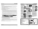
Mecanismo de Seguridad del
Disparo Secuencial
La NB0030 viene equipada con un
mecanismo de seguridad de disparo
secuencial. Cuando el operador pre-
siona el Elemento de Contacto de
Trabajo contra la superficie de trabajo
y luego aprieta el gatillo, se clavará un
sujetador.
5.
Presione el Elemento
de Contacto de
Trabajo contra la
superficie de trabajo
sin apretar el gatillo.
La clavadora NO DEBE OPERAR. No
use la herramienta si opera sin apre-
tar el gatillo. Se pueden producir
lesiones personales.
6. Remueva la clavadora
de la superficie de
trabajo. El Elemento
de Contacto de
Trabajo tiene que
volver a su posición original. La
clavadora NO DEBE OPERAR. No
use la herramienta si opera mien-
tras está levantada de la superficie
de trabajo.
7. Apriete el
gatillo y pre-
sione el
Elemento de
Contacto de Trabajo contra la
superficie de trabajo. La clavadora
DEBE OPERAR.
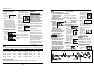
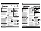
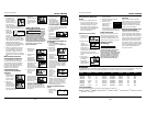
PARA CARGAR Y DESCARGAR LA
CLAVADORA
1. Siempre conectela herramienta a
la fuente de suminsitro de aire
antes de colocarle los clavos.
2. Presione el
pestillo de aliv-
io hacia abajo.
Mueva la tapa
del cargador
hacia atrás.
3. Coloque una
serie de clavos
Campbell
Hausfeld o equiv-
alentes (Vea la
sección de clavos) en el cargador.
Cerciórese de que los extremos pun-
tiagudos de los clavos estén hacia la
parte inferior del cargador.
Cerciórese de que los clavos no
estén sucios ni dañados.
4. Tire la tapa del
cargador hacia
adelante hasta
que calce el
pestillo.
5. Siempre
descargue el sujetador antes de
remover la herramienta de servicio.
La descarga se hace siguiendo el
proceso inverso de la carga; sin
embargo, siempre se tiene que
desconectar la manguera de aire
antes de descargarla.
CÓMO OPERAR LA CLAVADORA DE DIS-
PARO SECUENCIAL
1. Suelte el gatillo y
ponga la boca de
la herramienta
contra la superfi-
cie de trabajo.
2. Presione el
Elemento de
Contacto de
Trabajo contra la
superficie de tra-
bajo y apriete el
gatillo para clavar un sujetador.
3. Suelte el gatillo y
levante la her-
ramienta de la
superficie de tra-
bajo después de
clavar cada sujeta-
dor.
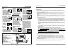
COMO CHEQUEAR EL ELEMENTO DE
CONTACTO
Chequée
el fun-
cionamiento del mecanismo del ele-
mento de contacto antes de cada uso.
El elemento de contacto se debe
desplazar libremente, sin pegarse, a lo
largo del área de desplazamiento. El
resorte del elemento de contacto debe
regresar el elemento de contacto a su
posición original totalmente extendido.
No use la clavadora si el mecanismo del
elemento de contacto no está funcio-
nando adecudamente. Podría ocasion-
arle heridas.
1.
Desconecte la
clavadora de la
fuente de su-
ministro de aire.
2. Saque todos
los clavos del
cargador (Vea
la Sección
Carga-
Descarga)
3. Cerciórese de que
el gatillo y el ele-
mento de contacto
se muevan libre-
mente en ambos
sentidos sin atas-
carse o pegarse.
4. Reconecte la
clavadora a la
fuente de sumin-
istro de aire.
!
PRECAUCION
Modelo IFN03000
Manual de Instrucciones
4-Sp
4,14 bar
Min.
6,9 bar
Max.
150 PSI WP
150 PSI WP
3/8" I.D.
3/8" I.D.
1,27 cm diam. int.
10,34 bar WP
Pestillo
movemiento
Pestillo
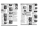
7. Depress the
work contact
element
(WCE) against
the work sur-
face. Pull the trigger. The nailer
MUST cycle.
LOADING/UNLOADING THE NAILER
1. Always connect the tool to the air
supply before loading fasteners.
2. Lift up on the
latch. Pull back
on the maga-
zine cover.
3. Insert a stick of
Campbell
Hausfeld nails or
equivalent (See
Fastener Section)
into the magazine. Make sure the
pointed ends of the nails are resting
on the bottom ledge of the maga-
zine when loading. Make sure the
nails are not dirty or damaged.
4. Push the maga-
zine cover for-
ward until the
latch
catches.
5. Unloading is the reverse of loading,
except always disconnect the air
hose before proceeding.
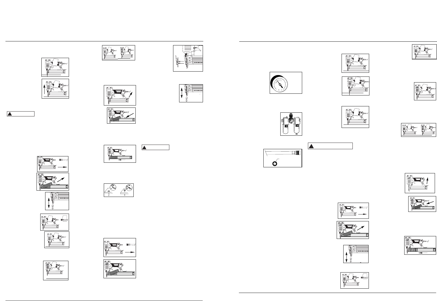
ADJUSTING THE NAIL PENETRATION
1. Regulate the
air pressure to
60 psi at the
nailer.
2. Connect the air supply and test for
penetration by driving nails into a
sample piece of wood. If the nails
do not achieve the desired penetra-
tion, adjust the air pressure to a
higher setting until the desired pen-
etration is achieved. Do not exceed
100 psi at the nailer or durability of
the nailer will be reduced.
CLEARING A JAM FROM THE NAILER
1. Disconnect the
air supply from
the
nailer.
2. Remove all
nails from the
magazine (See
Loading/
Unloading The
Nailer). Failure
to do so will cause the nails to eject
from the front of the nailer when
the nose assembly is removed.
Sequential Trip Safety
Mechanism (Cont.)
2. Depress the Work
Contact Element
(WCE) against the
work surface and
pull the trigger to
drive a fastener.
3. Release the trigger
and lift the tool
from the work sur-
face after each fas-
tener is driven.
CHECKING THE WORK CONTACT
ELEMENT (WCE)
Check the opera-
tion of the Work
Contact Element (WCE) trip mechanism
before each use. The WCE must move
freely without binding through its
entire travel distance. The WCE spring
must return the WCE to its fully
extended position after being
depressed. Do not operate the nailer if
the WCE trip mechanism is not operat-
ing properly. Personal injury may
occur.
1. Disconnect the
air supply from
the nailer.
2. Remove all
nails from the
magazine (See
Loading-
Unloading)
3. Make sure the trig-
ger and work contact
element (WCE) move
freely up and down
without sticking or
binding.
4. Reconnect air
supply to the
nailer.
5. Depress the work
contact element
(WCE) against the
work surface with-
out pulling the
trigger. The nailer MUST NOT cycle.
Do not use the nailer if it cycles.
Personal injury could result.
6. Hold the nailer
clear of the work
surface. The work
contact element
(WCE) should
return to its origi-
nal down position. Pull the trigger.
The nailer MUST NOT cycle. Do not
use the nailer if a cycle occurs.
Personal injury could result.
!
CAUTION
3. Pull red tab for-
ward on quick
clear nose. Set
aside nose door
to expose and
remove jammed
fastener.
4. Reinstall nose in reverse order in
step 3.
5. Make sure the trig-
ger and Work
Contact Element
(WCE) move freely
up and down with-
out sticking or binding.
TECHNICAL SUPPORT
Please call our Tool Hotline at 1-800-
543-6400 with any questions regarding
the operation or repair of this tool or
for additional copies of this manual.
Fastener and Replacement
Parts
Use only
genuine Campbell
Hausfeld 18 gauge fasteners (or equiva-
lent - see Fastener Interchange
Information). Tool performance, safety
and durability could be reduced if
improper fasteners are used. When
ordering replacement parts or fasten-
ers, specify by part number.
Tool Repair
Only qualified personnel should repair
the tool, and they should use genuine
Campbell Hausfeld replacement parts
and accessories, or parts and accessories
which perform equivalently.
Assembly Procedure For
Seals
When repairing a nailer, the internal
parts must be cleaned and lubricated.
Parker O-lube or equivalent must be
used on all o-rings. Each o-ring must be
coated with O-lube before assembling.
A small amount of oil must be used on
all moving surfaces and pivots. After
reassembling, a few drops of 30W non-
detergent oil or equivalent, must be
added through the air line before test-
ing.
!
WARNING
Latch
Model IFN03000
Operating Instructions
4
movement
movement
Latch
www.chpower.com