


23 Sp
Guía de diagnóstico de averías (Continuación)
Problema Posible(s) Causa(s) Acción a tomar
1. Conexiones flojas (conexiones,
tuberías, etc.)
2. La llave de drenaje está floja
3. Hay una fuga en la válvula de
chequeo
1. El filtro de entrada está obstruído
2. Hay fugas de aire en las tuberías (del
compresor o del sistema de conexión)
3. Las válvulas de entrada están
dañadas
4. El anillo del pistón está dañado
5. El cilindro o anillo del pistón está
desgastado o rayado
1. Exceso de agua en el tanque
2. Humedad alta
1. El presostato está dañado
2. Consumo excesivo de aire
1. Condensación excesiva en el tanque
2. Hay fugas de aire en las tuberías (del
compresor o del sistema de conexión)
3. Fuga en la válvula de chequeo del
tanque
La válvula de chequeo está atascada y
no se puede cerrar
1. Chequée todas las conexiones con agua enjabonada y
apriételas
2. Apriétela
3. Desmantele la válvula de chequeo, límpiela o
reemplácela
Antes de desmantelar
la válvula de
chequeo purgue el aire del tanque
1. Límpielo o reemplácelo
2. Reemplace las tuberías que tengan fugas o apriételas
según sea necessario
3. Un técnico especializado debe reparar el compresor
4. Reemplácelo
5. Reemplácelo
1. Drene el tanque
2. Mueva el compresor a una área menos húmeda; use
un filtro de aire incorporado a la línea
1. Reemplace el presostato
2. Disminuya el consumo de aire; el compresor es muy
pequeño para suministrar el aire requerido
1. Drénelo con más frecuencia
2. Reemplace las tuberías que tengan fugas o apriételas
según sea necessario
3. Reemplácela o repárela según sea necesario
Antes de desmantelar
la válvula de
chequeo purgue el aire del tanque
Desconecte y reemplace la válvula de chequeo
Antes de desmantelar
la válvula de
chequeo purgue el aire del tanque
!
PELIGRO
!
PELIGRO
!
PELIGRO
La presión del tanque
baja cuando el
compresor se apaga
La salida de aire es
inferior a la normal/la
presión de salida es baja
Exceseso de humedad
en el aire expulsado
El compresor funciona
continuamente
El compresor se
enciende y se apaga
automáticamente con
mucha frecueneia
Hay una fuga de aire en
el sistema de desfogue
del presostato
Serie WL
2
Oilless Compressors
3.Only persons well acquainted with
these rules of safe operation should
be allowed to use the compressor.
4.Keep visitors away and NEVER allow
children in the work area.
5.Wear safety glasses and use hearing
protection when operating the
pump or unit.
6.Do not stand on or use the pump or
unit as a handhold.
7.
Before each use, inspect compressed
air system and electrical components
for signs of damage, deterioration,
weakness or leakage. Repair or
replace defective items before using.
8. Check all fasteners at frequent
intervals for proper tightness.
Motors, electrical
equipment and controls
can cause electrical arcs
that will ignite a flammable gas or
vapor. Never operate or repair in or
near a flammable gas or vapor. Never
store flammable liquids or gases in the
vicinity of the compressor.
Compressor parts may
be hot even if the unit
is stopped.
9. Keep fingers away from a running
compressor; fast moving and hot
parts will cause injury and/or burns.
10.If the equipment should start to
abnormally vibrate, STOP the
engine/motor and check
immediately for the cause. Vibration
is generally a warning of trouble.
11.To reduce fire hazard, keep
engine/motor exterior free of oil,
solvent, or excessive grease.
Never remove or
attempt to adjust
safety valve. Keep safety valve free
from paint and other accumulations.
Never attempt to repair
or modify a tank!
!
DANGER
!
WARNING
!
CAUTION
!
WARNING
Welding, drilling or any other
modification will weaken the tank
resulting in damage from rupture or
explosion. Always replace worn or
damaged tanks.
Drain liquid from
tank daily.
13.
Tanks rust from moisture build-up,
which weakens the tank. Make sure
to drain tank regularly and inspect
periodically for unsafe conditions
such as rust formation and corrosion
.
14. Fast moving air will stir up dust and
debris which may be harmful. Release
air slowly when draining moisture or
depressurizing the compressor system.
SPRAYING PRECAUTIONS
Do not spray flammable
materials in vicinity of
open flame or near
ignition sources including the
compressor unit.
15.Do not smoke when spraying paint,
insecticides, or other flammable
substances.
16.Use a face mask/
respirator when
spraying and spray in
a well ventilated area
to prevent health and
fire hazards.
17.Do not direct paint or other sprayed
material at the compressor. Locate
compressor as far away from the
spraying area as possible to
minimize overspray accumulation
on the compressor.
18.When spraying or cleaning with
solvents or toxic chemicals, follow
the instructions provided by the
chemical manufacturer.
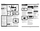
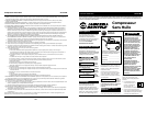
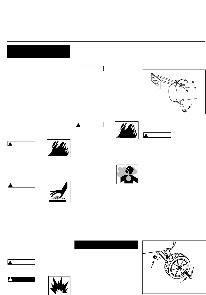
Compressor handle has a notch (or
detent) at top of handle. This notch
provides a handy place to hang a spray
gun, sandblast gun, or other tool
equipped with a hook.
1. Insert handle into both sides of tank
baseplate at motor end. Handle must
fit into special openings in baseplate
and must be squeezed by hand to fit.
!
WARNING
NOTICE
2. Place a short piece of wood against
end of handle and tap it with a
mallet or hammer to drive handle
into baseplate until hole in handle
and baseplate line up (See Fig. 1).
3. Assemble and tighten screw (from
parts package) through hole in base-
plate ensuring it goes through handle.
Never use the
handle to lift the
unit completely off the ground. Only
use the handle to lift one end so the
wheels may be used to move the unit.
4. Spread openings in the rubber feet
and slip over ground iron. Position
the feet as shown in Fig. 1.
WHEEL ASSEMBLY
The items marked with an asterisk (*)
were shipped loose with the unit.
1. Insert shoulder bolt through wheel
hub. The bolt hex head should be
on the opposite side of protruding
hub center.
2. For 8 inch diameter wheels, feed
the shoulder bolt through the
bottom hole on the tank axle iron
and tightly secure with the locknut.
For 10 inch diameter wheels, feed
the shoulder bolt through the top
hole on the tank axle iron and
tightly secure with the locknut.
!
WARNING
Figure 1
Rubber
Foot
General Safety
Information (Continued)
Assembly
Shoulder
bolt
*
*
Figure 2 - Wheel Assembly
Lock nut
Wheel
www.chpower.com