


Symptom Possible Cause(s) Corrective Action
Air leaking at trigger valve
area.
O-Rings in trigger valve housing are
damaged
Replace o-rings
Air leaking between housing
and nose.
1. Damaged o-rings 1. Replace o-rings
2. Damage to bumper 2. Replace bumper
Air leaking between housing
and cap.
1. Loose screws 1. Tighten screws
2. Damaged seal 2. Replace seal
Tool skips driving fastener 1. Worn bumper 1. Replace bumper
2. Dirt in nose piece 2. Clean drive channel
3. Dirt or damage prevent fasteners or
pusher from moving freely in magazine
3. Clean magazine
4. Damaged pusher spring 4. Replace spring
5. Inadequate air flow to tool 5. Check fitting, hose, or compressor
6. Worn o-rings on piston or lack of
lubrication
6. Replace and lubricate o-rings
7. Damaged o-rings on trigger valve 7. Replace o-rings
8. Air leaks 8. Tighten screws and fittings
9. Cap seal leaking 9. Replace seal
10. Defect in automatic nail length plate 10. Clear problem with plate
Tool runs slow or has loss of
power
1. Tool not lubricated sufficiently 1. Lubricate nailer
2. Broken spring in cylinder cap 2. Replace spring
3. Exhaust port in cap is blocked 3. Replace damaged internal parts
Fasteners are jammed in tool 1. Guide on driver is worn 1. Replace guide
2. Fasteners are not correct size 2. Use only recommended fasteners
3. Fasteners are bent 3. Replace with undamaged fasteners
4. Magazine or nose screws are loose 4. Tighten screws
5. Driver is damaged 5. Replace driver
Troubleshooting Chart
Stop using tool immediately if any of the following problems occur. Serious personal injury could occur.
Any repairs or replacements must be done by a Qualified Service Person or Authorized Service Center.
6
Operating Instructions
USER-MAINTENANCE
INSTRUCTIONS (CONTINUED)
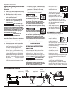
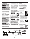
Replace assembly by first removing
the four (4) head cap screws using the
3 mm hex wrench provided. Remove
head cap and components to access the
driver piston. Remove and replace driver
assembly using your fingers. Replace
components and head cap as removed.
ASSEMBLY PROCEDURE FOR SEALS
When repairing a tool, the internal
parts must be cleaned and lubricated.
Parker O-lube or equivalent must be
used on all o-rings. Each o-ring must be
coated with O-lube before assembling.
A small amount of oil must be used on
all moving surfaces and pivots. After
reassembling, a few drops of 30W
non-detergent oil or equivalent, must
be added through the air line before
testing.
STORAGE
The tool should be stored in a cool dry
place.
Interchange Information
Can use 3/8 inch to 7/8 inch pins
from the following branded 23 g
micropinners: Senco FP10, Air Locker
P630, Porter Cable PIN100, Grex P635,
and Max NF235A.
www.chpower.com