2
Operating Instructions and Parts Manual
Low Oil Guard
for 5 to 25 HP Compressors
Installation (Continued)
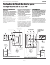
guard must be tested to verify proper
installation. Before refilling crankcase
with oil, briefly turn on power to the
compressor motor (2-3 seconds max.).
NOTE: Some oil film remains on the lu-
bricated parts of the compressor.
Running the compressor dry for 2-3 sec-
onds will not cause any damage.
If motor does not run, installation is
correct. If motor begins to run, turn
power off immediately. The installation
is wrong and the following items
should be checked:
1. Check for loose wire connections.
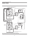
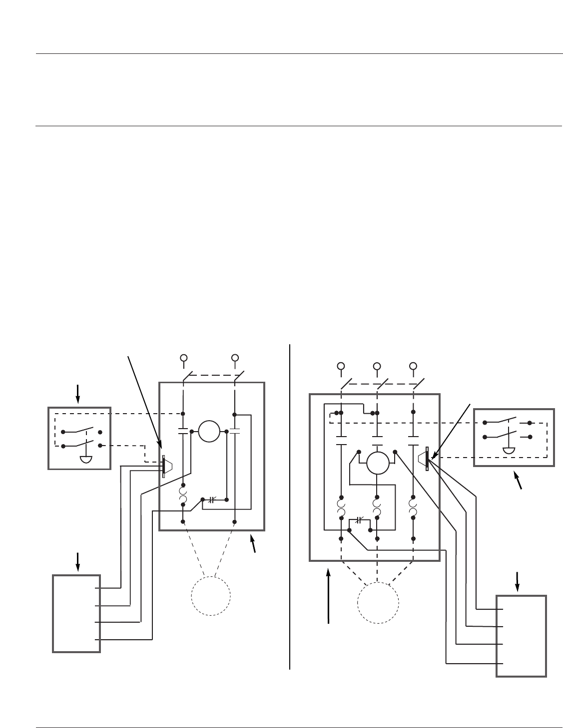
2. Check for wrong wiring (Refer to
Figure 4, 5 or 6).
3. Check to see if the float mechanism is
moving freely.
4. Check the compressor for a level
position.
After the monitor installation has been
tested and found correct, refill the com-
pressor pump with compressor oil. For
complete information on compressor
pump oil, see your compressor pump
manual.
TF0628
PRESSURE
SWITCH
FUSED DISCONNECT
OR BREAKER
RED
ORANGE
WHITE
BLACK
OIL
LEVEL
GUARD
L2
L1
O.L.
MAGNETIC
STARTER
T2T1
SINGLE
PHASE
MOTOR
COIL
PRESSURE
SWITCH
FUSED DISCONNECT
OR BREAKER
RED
ORANGE
WHITE
BLACK
OIL
LEVEL
GUARD
L3L2
O.L.
MAGNETIC
STARTER
T2T1 T3
L1
THREE
PHASE
MOTOR
COIL
Operation
In normal operation, the low oil-level
monitor should not have any effect on
the performance of the compressor. If
the oil level in the pump is too low, the
monitor will shut off power to the
motor, stopping the compressor pump.
Maintenance
The operation of the low oil-level mon-
itor should be checked at every oil
change. After the oil has been drained
from the crankcase, repeat the initial
test as previously described.
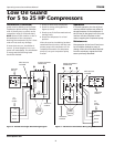
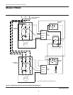
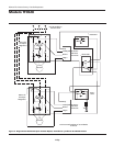
Figure 4 - 208-230 Volt Single-Phase Wiring Diagram
Figure 5 - 208-230 Volt Three-Phase Wiring Diagram
Wire nut not
included
Wire nut not
included
www.chpower.com


