


2
Piping Connections —
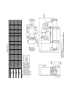
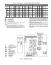
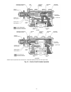
Attach water supply and return
lines to connections indicated on condensing unit (Fig. 2).
Water leaving condenser should not be connected directly into
sewer lines; check local codes.
Attach refrigerant liquid and suction lines to condensing
unit (Fig. 2); suction and discharge lines to compressor unit
(Fig. 3 and 4). Discharge line muffler and check valve are
factory supplied with 06E compressor units. Install the muffler
as close to shutoff valve as possible and install the check valve
in the discharge line close to the muffler, on the downstream
side. When soldering or brazing piping to valves, disassemble
the valve or wrap it in wet cloth to prevent damage by heat.
Allow flexibility in suction line so compressor suction valve
may be moved aside for access to suction strainer.
A solenoid valve is necessary for single pumpout control
used on 06E and 07E units. Install the valve (field supplied) in
the liquid line, just before expansion valve. A filter drier of
adequate size should be installed in liquid line between con-
denser and solenoid valve.
Pressure relief valve located on top of condenser will open
to relieve excessive pressure, allowing refrigerant to escape.
Most local codes require piping from valve to outdoors.
Refer to Carrier System Design Manual for standard piping
techniques.
Electrical Connections
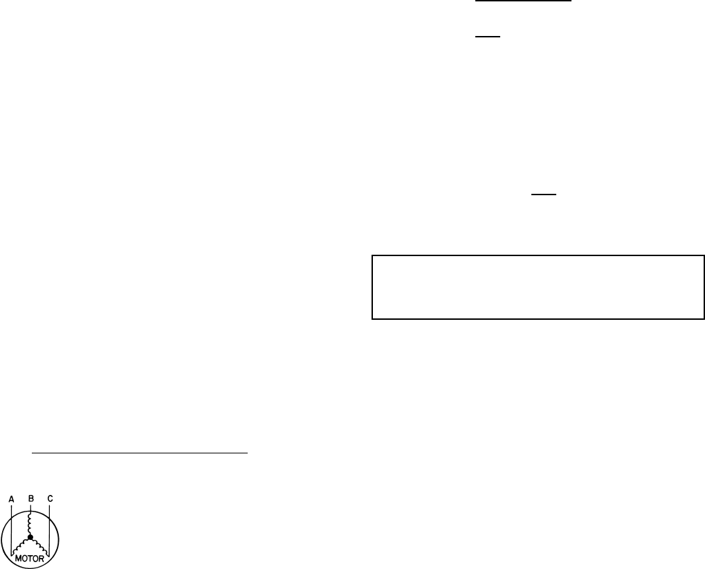
UNBALANCED 3-PHASE SUPPLY VOLTAGE — Never
operate a motor where a phase imbalance in supply voltage
is greater than 2%. Use the following formula to determine
the % voltage imbalance:
% Voltage Imbalance =
Example: Supply voltage is 240-3-60
AB = 243 volts
BC = 236 volts
AC = 238 volts
Determine maximum deviation from average voltage:
(AB) 243 – 239 = 4 volts
(BC) 239 – 236 = 3 volts
(AC) 239 – 238 = 1 volt
Maximum deviation is 4 volts. Determine % voltage
imbalance:
This amount of phase imbalance is satisfactory as it is below
the maximum allowable 2%.
POWER SUPPLY — Field wiring must comply with local
and national codes. See Table 1.
Install a branch circuit fused disconnect of adequate size to
handle starting current. The disconnect must be within sight
from the unit and readily accessible, in compliance with
National Electrical Code (NEC), Section 440-14.
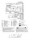
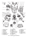
Line power is brought into control center through indicated
opening. Connect line power supply to terminal block TB1;
connect power leads to terminals L1, L2 and L3. Connect
control circuit power supply (115 volts) to terminals 1 and 15
on terminal block TB2. Refer to Fig. 5.
Wiring connections for field-supplied equipment are shown
on wiring diagram. See Fig. 6.
ACCESSORIES — Field-installed accessories for the 06E
and 07E units are control circuit transformer and gage
panel (3 gages). Refer to accessory literature for installation
instructions.
100 x
max voltage deviation from avg voltage
average voltage
Average Voltage =
243 + 236 + 238
3
=
717
3
=
239 volts
% Voltage Imbalance = 100 x
4
= 1.7%
239
IMPORTANT: If the supply voltage phase imbalance is
more than 2%, contact your local electric utility company
immediately. Allowing the unit to operate with a voltage
imbalance in excess of 2% may void the warranty.